 FREE 1 to 3-Day Delivery on Orders $119+ Details
How to Install SkyJacker 4.5 in. Suspension Lift Kit w/ Hydro Shocks on your F-150
Installation Time
1 days
Tools Required
- T527823-manu
- Metric / Standard Wrenches & Sockets
- Hex Key Wrenches
- Hammer / Punch / Locking Pliers
- Floor Jack / Jack Stands
- Drill / Assorted Drill Bits
- Measuring Tape
- Torque Wrench
- Reciprocating Saw / Grinder
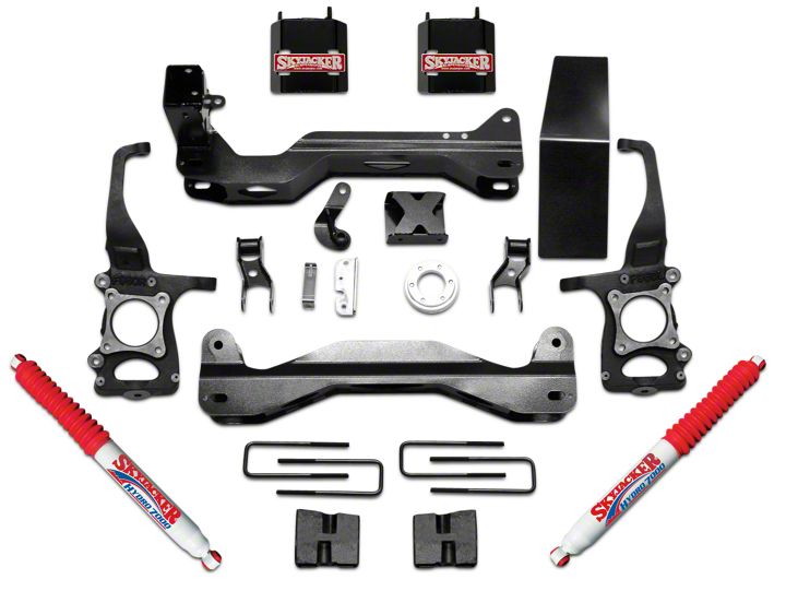
Shop Parts in this Guide
Front Installation:
1. With the vehicle on flat level ground, set the emergency brake & block the rear tires / wheels.
2. Place a floor jack under the lower control arm front cross member & raise the vehicle. Place jack stands under the frame rails, behind the front wheel wells & lower the frame of the vehicle onto the jack stands.
3. Remove the front tires / wheels.
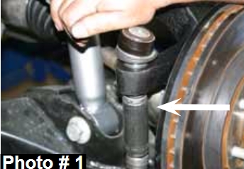
4. Disconnect the OEM outer tie rod ends from the OEM steering knuckles using a 21mm socket & tie rod remover or other suitable tool. (See Photo # 1)
5. Remove the OEM brake line brackets & OEM brake caliper mounting bolts from the OEM steering knuckles. Remove the OEM brake caliper assemblies & simply wire the OEM brake caliper assemblies out of the way. It will not be necessary to disconnect the OEM brake lines from the OEM brake caliper assemblies.
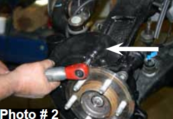
6. Remove the OEM brake rotors & remove the OEM disc brake shields using a 8mm socket. (See Photo # 2)
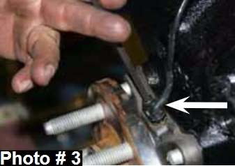
7. Remove the OEM ABS sensors & OEM ABS sensor brackets from the OEM steering knuckles using a 5mm hex key & 8mm socket. (See Photo # 3)
8. Disconnect the OEM intergrated vaccum lines from the OEM 4WD actuator & the upper frame connection.
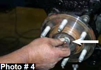
9. Remove the OEM cv-shaft nuts from the center of the OEM hub assemblies using a 13mm socket. (See Photo # 4)
10. Disconnect the OEM upper sway bar end links using a 18mm socket. Remove the OEM sway bar & OEM sway bar mounting brackets from the frame using a 15mm socket.
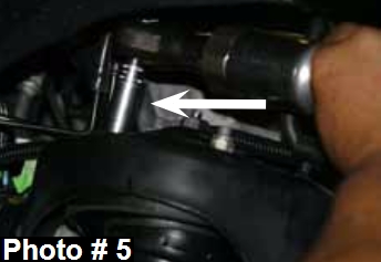
11. Remove the three OEM upper strut retaining nuts from each OEM strut assembly using a 15mm socket. (See Photo # 5)
12. Remove the OEM upper & lower ball joints from the OEM steering knuckles using a 1", 22mm socket, & ball joint remover or other suitable tool.
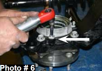
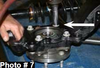
13. Remove the OEM steering knuckles. Once removed, remove the three OEM 4WD actuator bolts & the four OEM hub bearing assembly bolts from the OEM steering knuckles using a 8mm & 18mm socket. (See Photos # 6 & # 7)
14. Remove the OEM lower strut mount bolts from the OEM lower control arms using a 1 1/16" & 1 3/16" socket. Once removed, remove the OEM strut assemblies.
15. Remove the OEM front & rear lower control arm bolts using a 21mm & 1 1/6" socket. Once removed, remove the OEM lower control arms.
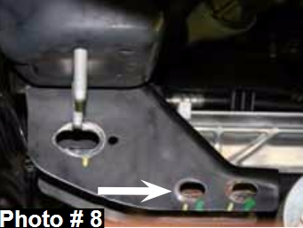
16. Remove the four OEM rear cross member frame connecting bolts using a 15mm socket & remove the OEM rear cross member. (See Photo # 8)
17. Mark the position of the OEM front differential flange & OEM drive shaft flange. Note: These marks will be realigned during reassembly. Remove the six OEM front drive shaft mounting bolts from the OEM front differential using a 10mm socket. It will not be necessary to remove the OEM drive shaft from the OEM transfer case. Simply wire the OEM drive shaft out of the way.
18. Support the OEM front differential with a transmission jack & remove the OEM differential mounting bolts using a 18mm & 21mm socket. There are two on the driver side (Front & Rear) & one on the passenger side. Once these bolts are removed, lower the OEM front differential out of the vehicle.
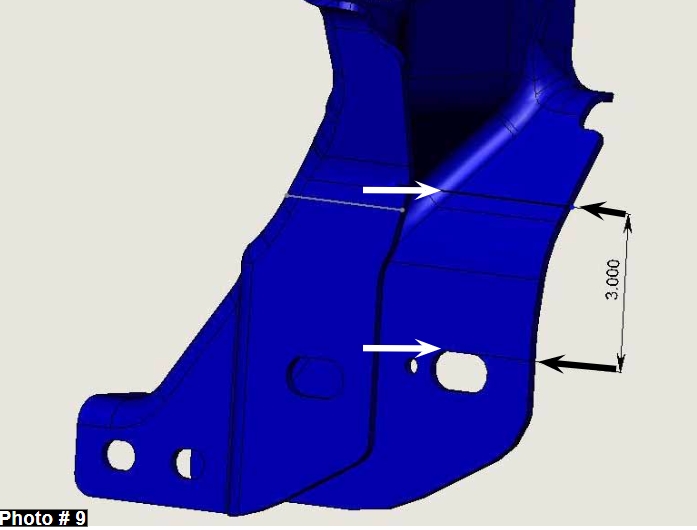
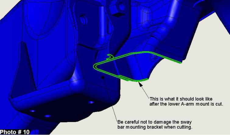
19. It will now be necessary to cut the OEM rear cross member for differential clearance when the lift is installed. Locate the OEM driver side rear cross member bracket, measure from the top of the slotted hole of the OEM bracket up 3" & draw a straight line along the front outer edge of the OEM bracket. This process will need to be completed on the rear side of the OEM bracket as well. (See Photo # 9) Connect the two lines drawn on the front & rear sides of the OEM bracket in order to have a single cutting reference line. Cut along the drawn line using a grinder or reciprocating saw. Refer to the picture provided for an example of what the OEM bracket will look like once cut. (See Photo # 10)
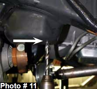
20. Drill the two OEM sway bar mounting bracket holes located on the driver side frame using a drill & 1/2" drill bit. (See Photo # 11)
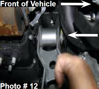
21. Install the new Skyjacker driver side (Part # F960DDB-B) & passenger side (Part # F960PDB-B) front differential brackets in the OEM location with the offset of the new brackets facing toward the front of the vehicle, using the OEM hardware & 18mm wrench. Do not tighten at this time. (See Photo # 12)
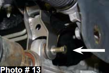
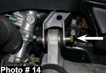
22. Support the OEM front differential with a transmission jack & install the OEM front differential. Install the two supplied 14mm x 90mm bolts, two 9/16" washers, & two 14mm nuts in the lower mounting location of the new Skyjacker driver & passenger side front differential brackets using a 21mm socket & 22mm wrench. Note: The supplied 9/16" washers are to be installed on the hex head side of the supplied 14mm x 90mm bolts. Do not tighten at this time. (See Photos # 13 & # 14)
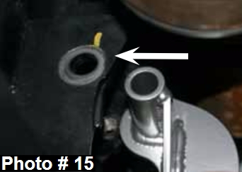
23. Install the new Skyjacker driver side rear differential bracket in the OEM location with the flat side of the new bracket facing toward the front of the vehicle, using the OEM hardware & a 21mm wrench. Do not tighten at this time. (See Photo # 15)
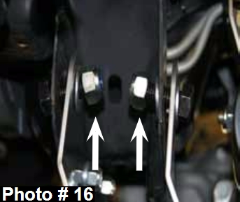
24. Install the new Skyjacker rear cross member, with the driver side intergrated sway bar lowering bracket facing toward the rear of the vehicle. Install the two supplied 18 x 50mm bolts, four 3/4" washers, & two 18mm nuts in the passenger side upper two holes of the new rear cross member using a 1 1/6" socket & wrench. Do not tighten at this time. (See Photo # 16)
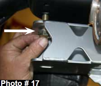
25. Install the two supplied 1/2" x 1 1/2" bolts, four 1/2" washers, & two 1/2" nuts in the two holes of the new Skyjacker intergrated sway bar lowering bracket using a 3/4" socket & wrench. Do not tighten at this time. (See Photo # 17)
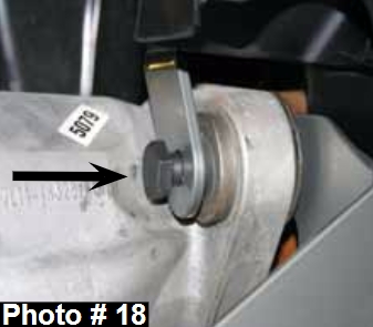
26. Install the supplied 14mm x 90mm bolt & 14mm nut in the lower mounting hole of the new Skyjacker driver side rear differential bracket & rear cross member using a 21mm socket & 22mm wrench. Do not tighten at this time. (See Photo # 18)
27. Install the two supplied 1/2" x 1 1/2" bolts, four 1/2" washers, & two 1/2" nuts in the two rear holes of the passenger side OEM cross member bracket & new Skyjacker cross member using a 3/4" socket & wrench. Do not tighten at this time.
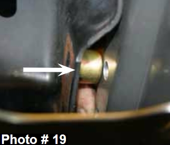
28. Install the two supplied 13/16" long crush sleeves, two 1/2" x 2" bolts, four 1/2" washers, & two 1/2" nuts in the two front holes of the passenger side OEM cross member bracket & new Skyjacker cross member using a 3/4" socket & wrench. Do not tighten at this time. (See Photo # 19)
29. Tighten the two 1/2" x 1 1/2" bolts & two 1/2" nuts located on the new Skyjacker intergrated sway bar lowering bracket using a 3/4" socket & wrench.
30. Tighten the two 18mm x 50mm bolts & two 18mm nuts in the passenger side upper rear cross member using a 1 1/6" socket & wrench. 31. Tighten the two 1/2" x 1 1/2" bolts, two 1/2" x 2" bolts & four 1/2" nuts of the front & rear passenger side OEM cross member bracket & new Skyjacker cross member using a 3/4" socket & wrench.
32. Tighten the 14mm x 90mm bolt, 14mm nut, & OEM bolt on the upper & lower mounting locations of the new Skyjacker driver side rear differential bracket & rear cross member using a 21mm socket & 22mm wrench.
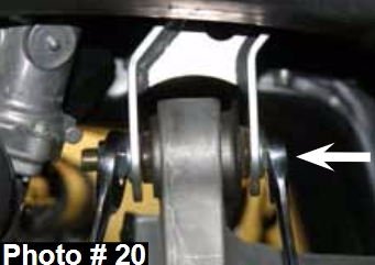
33. Tighten the two 14mm x 90mm bolts, two 14mm nuts, OEM hardware on the upper & lower mounting locations of the new Skyjacker driver & passenger side front differential brackets using a 21mm socket, 18mm, & 22mm wrench. (See Photo # 20)
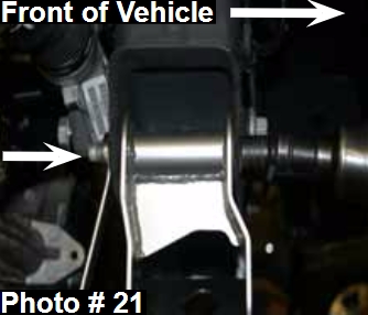
34. Install the new Skyjacker front cross member with the offset facing toward the front of the vehicle. Install the OEM hardware in the upper two holes of the new Skyjacker cross member using a 21mm & 1 1/6" socket. (See Photo # 21)
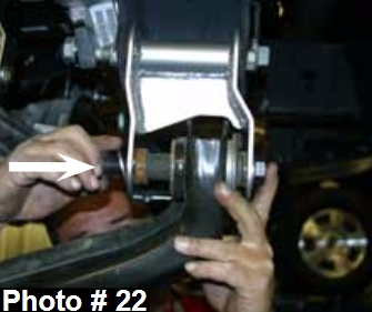
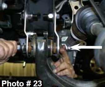
35. Install the two supplied 18mm x 160mm bolts, four 3/4" washers, & two 18mm nuts on the the lower front cross member mounts & lower control arms using a 21mm & 1 1/6" socket. (See Photo # 22) Install the two supplied 18mm x 150mm bolts, four 3/4" washers, & two 18mm nuts on the the lower rear cross member mounts & lower control arms using a 21mm & 1 1/6" socket. (See Photo # 23)
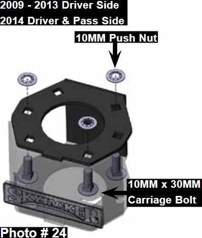
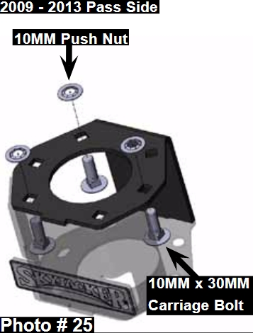
36. Assemble the new Skyjacker strut spacers using the supplied 10mm x 30mm carriage bolts & 10mm push nuts. (See Photos # 24 & # 25) Note: For 2009-2013 models, assemble the new strut spacers using the bolt location diagram in Photo # 24 for the driver side & Photo # 25 for the passenger side. For 2014 models, assemble the new strut spacers using the bolt location diagram in Photo # 24 for both the driver & passenger side.
37. Install the new Skyjacker strut spacers on the top of each OEM strut assembly using the OEM hardware & a 15mm socket. Do not tighten at this time.
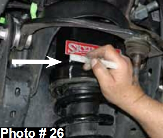
38. Install the strut / spacer assemblies & align the three studs of each new strut spacer with the OEM mounting locations. For alignment purposes, mark the location of the upper strut mount & new strut spacer. (See Photo # 26)
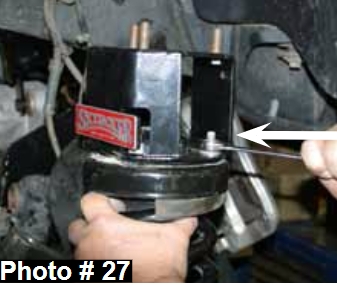
39. Remove the strut / spacer assemblies. Align the previously made marks & tighten the new strut spacers to the OEM strut assemblies using a 15mm socket. (See Photo # 27)
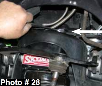
40. Install the strut / spacer assemblies by aligning the three upper strut mount studs with the OEM mounting locations using the supplied 10mm nuts & a 15mm socket. (See Photo # 28)
41. Install the OEM hub bearing assemblies to the new Skyjacker steering knuckles using the OEM hardware. Apply thread lock to the threads of each bolt & tighten using a 18mm socket. Note: Make sure that the OEM ABS sensor connection is pointing upward. (See Photo # 7)
42. Install the OEM 4WD actuators using the OEM hardware & a 8mm socket. Note: Make sure that the OEM hose connections are pointing upward. (See Photo # 6)
43. Install the new Skyjacker steering knuckles to the OEM lower control arm ball joints using the OEM hardware & a 1" socket.
44. Install the OEM lower strut mount using the OEM hardware, a 1 1/16", & 1 3/16" socket.
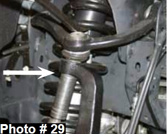
45. Install the OEM cv-shafts using the OEM hardware & a 13mm socket. Install the OEM upper ball joints to the new Skyjacker steering knuckles using the OEM hardware & a 22mm socket. Note: It may be necessary to use a jack to raise the OEM lower control arms in order to install the OEM upper ball joints. (See Photo # 29)
46. Install the OEM ABS sensors & ABS sensor brackets to the new Skyjacker steering knuckles using the OEM hardware, a 5mm hex key, 8mm socket, & supplied plastic ties. (See Photo # 3)
47. Install the new Skyjacker 7/64" & 5/32" vaccum lines for the OEM 4WD actuator & upper frame connection using the supplied plastic ties.
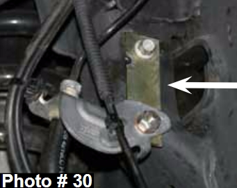
48. Disconnect the OEM front brake line brackets from the frame & install the new Skyjacker front brake line extension brackets using the OEM hardware & the supplied 1/4" x 1" bolts, nuts, & washers. (See Photo # 30)
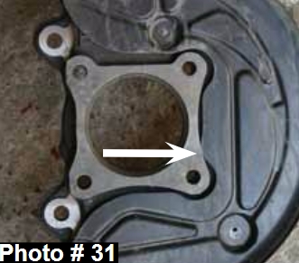
49. Install the OEM disc brake shields using the OEM hardware & a 8mm socket. Note: Some models may require the inside edge of the OEM disc brake shields to be ground in order for the OEM disc brake shields to fit flush to the new Skyjacker steering knuckles. (See Photo # 31)
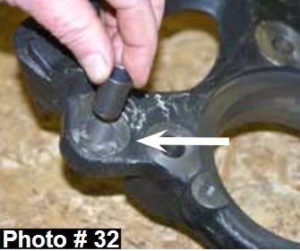
50. Install the OEM brake rotors, brake line brackets, & brake caliper assemblies using the OEM hardware. Note: If the OEM brake caliper mounting hardware is 14mm, place the supplied (two per side) reducer bushings (Part # 1416-BSG) in the OEM brake caliper mounting locations of the new Skyjacker steering knuckles before installing the OEM 14mm hardware. (See Photo # 32)
51. Install the OEM outer tie rod ends to the new Skyjacker steering knuckles using the OEM hardware & a 21mm socket. (See Photo # 1)
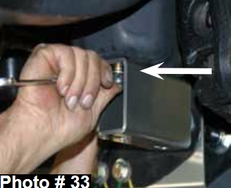
52. Using two supplied 7/16" x 1 1/2" bolts, four 7/16" washers, two 7/16" nuts, a 5/8" socket, & 5/8" wrench, install the new Skyjacker sway bar drop bracket on the passenger side frame of the vehicle. (See Photo # 33)
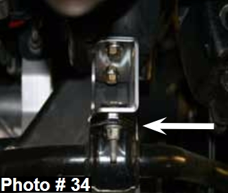
53. Install the OEM sway bar to the new Skyjacker sway bar lowering brackets using the OEM hardware & a 15mm socket. (See Photo # 34)
54. Connect the OEM sway bar end links to the OEM sway bar using the OEM hardware & a 18mm socket.
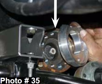
55. Install the new Skyjacker front drive shaft spacer with the male side facing the differential using the six supplied 10mm x 80mm socket head bolts, OEM retaining rings, & a 8mm hex key. Note: Apply thread lock to the threads of these bolts & be sure to align the previously made marks on the OEM front differential flange & OEM drive shaft flange. (See Photo # 35)
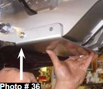
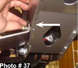
56. Hold the new Skyjacker front differential skid plate in place with the mounting holes of the new skid plate facing the rear of the new front & rear cross members. Using a hammer & punch, mark the four mounting hole locations. Drill the marked mounting location holes, using a drill & 5/16" drill bit. Using the four supplied 5/16" x 1" bolts, eight 5/16" washers, four 5/16" nuts, a 1/2" wrench, & 1/2" socket, install the new front differential skid plate. (See Photos # 36 & # 37)
Rear Installation:
1. With the vehicle on flat level ground, block the front tires / wheels.
2. Place a floor jack under the vehicle & raise the rear of the vehicle. Place the jack stands under the frame rails & lower the frame of the vehicle onto the jack stands.
3. Remove the rear tires / wheels.
4. Remove the OEM E-brake cable from the OEM cable union & remove the OEM E-brake cable from the driver side OEM bracket. Remove the OEM passenger side E-brake cable & relocate above the OEM rear leaf spring.
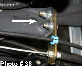
5. Install the new Skyjacker E-brake bracket using the supplied 3/8" x 1 1/4" bolt, two 3/8" washers, 3/8" nut, 1/2" x 1 1/2" bolt, two 1/2" washers, 1/2" nut, a drill, & 3/8" drill bit. Install the new E-brake bracket to the OEM upper hole using the supplied 1/2" hardware. Using the new Skyjacker E-brake bracket as a guide, drill a 3/8" hole just below the OEM upper hole & install the supplied 3/8" hardware. (See Photo # 38)
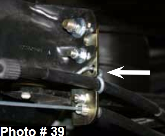
6. Install the OEM driver side E-brake cable to the lower hole of the new Skyjacker E-brake cable bracket & the OEM passenger side E-brake cable to the semi-circular hole of the new Skyjacker E-brake cable bracket. Note: Models with the OEM round plastic passenger side E-brake cable retainer, insert the OEM retainer into the semi-circular hole of the new E-brake cable bracket. (See Photo # 38) Models with the OEM metal wire passenger side E-brake cable retainer, insert the end of the OEM retainer thru the slotted hole of the new E-brake cable bracket & mount using the supplied 5/16" x 1" bolt, two 5/16" washers, & 5/16" nut. (See Photo # 39) Photo # 36 Photo # 37 Photo # 38 Photo # 39
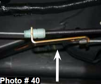
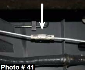
7. Install the OEM passenger side E-brake cable to the new Skyjacker E-brake extension bracket. Connect the OEM driver side E-brake cable to the rear slotted hole of the new E-brake extension bracket. Connect the E-brake cable assembly to the OEM cable union. (See Photos # 40 & # 41)
8. Remove the OEM rear shocks & disconnect the OEM rear brake line bracket from the frame rail using a 13mm, 15mm, & 18mm socket.
9. Support the rear axle & remove the rear OEM u-bolts using a 21mm socket.
10. 4.5" Lift: While checking for appropriate slack in ABS lines, brake lines, differential breather hose, & etc. Lower the rear axle & remove the OEM rear blocks. Install the new Skyjacker 4.5" rear lift blocks with the taller end of the new rear lift blocks toward the rear of the vehicle.
11. 6" Lift: While checking for appropriate slack in ABS lines, brake lines, differential breather hose, & etc. Lower the rear axle & install the new Skyjacker 4.5" rear lift blocks below the OEM rear blocks with the taller end of the new rear lift blocks toward the rear of the vehicle.
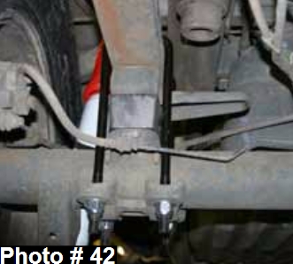
12. Raise the rear axle & install the new Skyjacker rear u-bolts using the supplied 9/16" nuts & a 7/8" socket. (See Photo # 42)
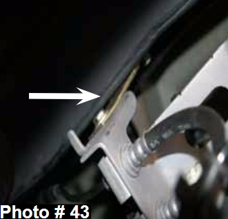
13. Install the new Skyjacker rear brake line bracket to the OEM mount on the frame rail using the OEM hardware & a 13mm socket. Connect the OEM brake line bracket to the new brake line bracket using the supplied 1/4" x 1" bolt, two 1/4" washers,1/4" nut, & a 7/16" socket & wrench. (See Photo # 43)
14. Install the new Skyjacker rear shocks using the supplied hardware, OEM hardware, a 15mm, & 18mm socket.
15. Install the rear tires / wheels & lower the rear of the vehicle to the ground.
Final Notes:
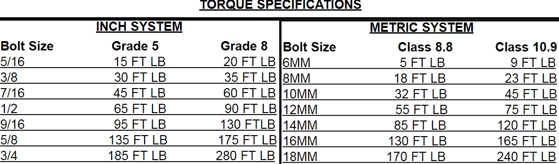
• After the installation is complete, double check that all nuts & bolts are tight. Refer to the following chart for the proper torque specifications. (Do not retighten the nuts & bolts where thread lock compound was used.)
• With the vehicle placed on the ground, cycle the steering lock to lock & inspect the steering, suspension, brake lines, front & rear drivelines, fuel lines, & wiring harnesses for proper operation, tightness, & adequate clearance.
• Have the headlights readjusted to the proper settings.
• Have a qualified alignment center align the vehicle to the OEM specifications.
• After the first 100 miles, check all of the hardware for the proper torque & periodically thereafter.
