FREE 1 to 3-Day Delivery on Orders $119+ Details
How to Install TracRac TracONE Truck Rack - Clamp On on your F-150
Installation Time
1 hours
Tools Required
- 3/16” Allen Key
- 7/32” Allen Key
- Tape Measure
- 9/16” Socket and Socket Wrench
- Torque Wrench
- 7/32” Allen Drive Bit
- Non-Impact Drill
Installation Instructions
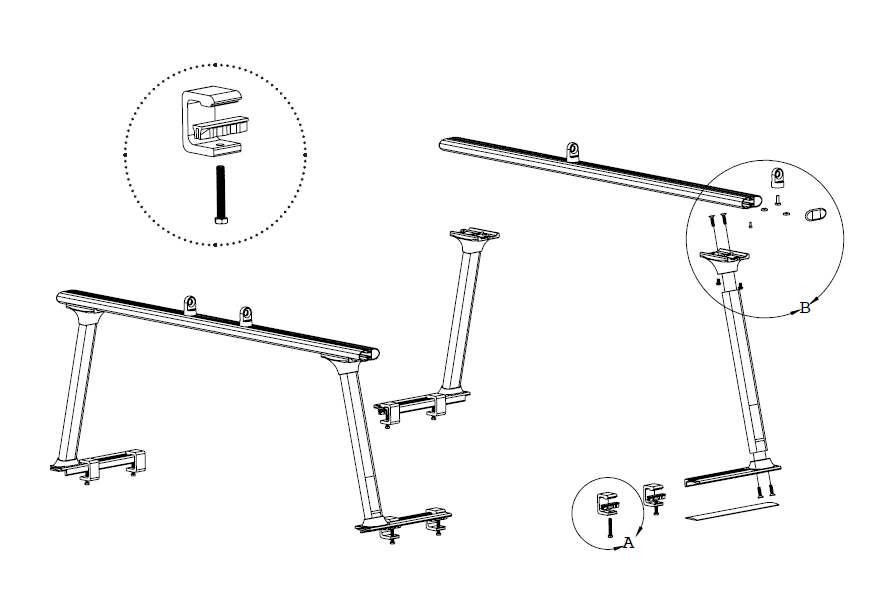
These instructions will guide you through the 3 main component assemblies:
1. Upright units
2. Cross bars
3. Clamp units
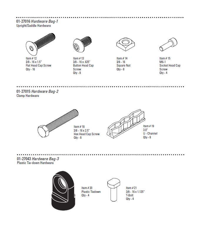
Hardware Bag Contents
Step 1
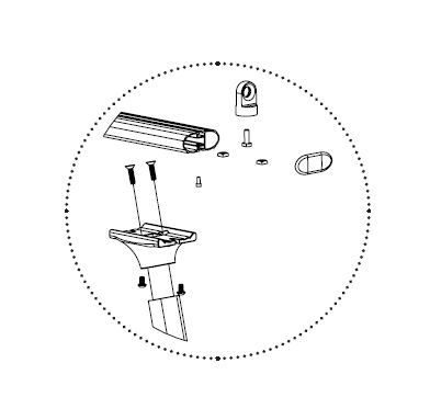
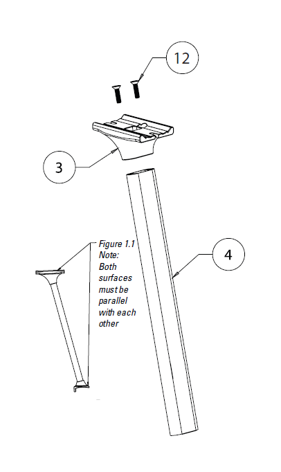
1.1 Upright Assembly
1. First take the upright (Item 4) and insert it into a modular saddle (Item 3).
2. Bolt the saddle through the top by using two 3/8”-16 flat head cap screws (Item 12) and tighten using an 7/32” Allen Wrench (or 7/32” Allen Drive Bit). Torque the 3/8” -16 FHCS to 32 ft-lbs. We recom-mend threading both flat head cap screw initially by hand to ensure that you don’t cross thread the bolt.
1.1.1 When tightening the 3/8” flat head cap screws ensure that the allen key is fully seated in the bolt so that it will not strip
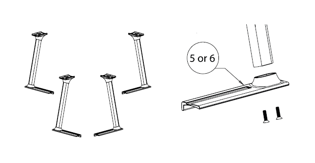
3. Now take the upright and saddle and bolt it to the modular base (Item 5)
4. Bolt the base through the bottom by using two 3/8”-16 flat head cap screws (Item 12) and tighten usingan 7/32” Allen Wrench (or 7/32” Allen Drive Bit.) Torque the 3/8” -16 FHCS to 32 ft-lbs.
5. For the other front upright repeat steps one through four, except use (Item 6) in step three.
6. Repeat Steps 1-5 on each of the uprights
1.1.2 NOTE: Item 5 and Item 6 are mirror images of each other. Reference the packing checklist to confirm what part to use.
Step 2
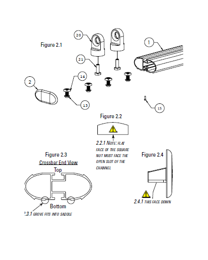
2.1 Crossbar Assembly
1. Take the double T-Slot crossbar (Item 1) and insert four square nuts (Item 14) into the bot-tom T-Slot. Reference Figure 2.1, 2.2 & 2.3
2. Insert a T-bolt (Item 21) through the bottom of the cross bar tie-down (Item 20) and slide the unit into the top track of the crossbar so that both the bolt and the tiedown are locked into the t-track.
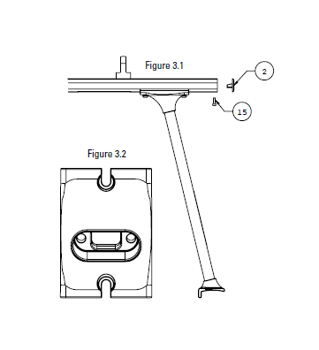
3. Insert the Crossbar End Cap with the flat mounting surface facing down into the end of the crossbar. Using the clearance hole on the bottom of the crossbar and the M6 SHCS (Item 15). Tighten down the M6 SHCS using a 3/16” Allen Key. Repeat on the opposite side. Reference Figure 3.1
4. Repeat steps 1-3 for the remaining crossbar.
Step 3
3.1 Front & Rear Crossbar Installation
1. Now place the assembled crossbar on top of the assembled uprights. Make sure the crossbar is right side up. Reference Figure 2.3
2. Slide the Square Nuts (Item 14) so that they are directly above the slotted hole in the saddle. Insert the 3/8 BHCS (Item 13) into the Square Nuts (Item 14) and tighten the cap screws, using an 7/32” Allen Wrench (or 7/32” Allen Drive Bit) Do not fully torque the screws until Step 8 of the Truck Installation
3.1.1 Note: Make sure that the BHCS sits completely within the recessed area of the saddle casting. See Figure 3.2
3. Repeat Steps 1 and 2 for the opposite upright.
4. Repeat Steps 1-3 for the remaining crossbar.
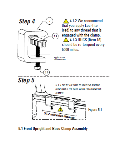
4.1 Base Clamp Assembly
1. Take a modular clamp (Item 7) and thread a 3/8”-16 hex head cap screw (Item 18) through the bottom as shown. (See note about Loc-Tite)
2. Now take a C channel clamp foot (Item 19) and place it on top of the 3/8” hex head cap screw as shown.
3. Repeat steps one and two for the remaining seven clamps.
4.1.1 Note: Clamp feet must be used to ensure proper clamping force distribution between the rack and the truck bed and prevent damage
5.1 Front Upright and Base Clamp Assembly
1. Now take the rounded shims (Item 8) and place them on the sidewalls of you truck approximately where the uprights will sit.
The front uprights will be directly behind the rear win-dow. Place the unit as far forward as possible
2. Place the front uprights on top of the rounded shims (Item 8) making sure that the rubber shims are completely under the bases.
3. With one pair of uprights now on the truck, they must be secured using two Modular Clamps (Step 4). When positioning the clamps make sure they are spaced as far apart as possible.
4. First torque the clamps on either side of the rack towards the cab, then follow with the other two clamps towards the rear of the truck
5. Torque down the HHCS to 14 lb-ft using a 9/16” socket and a torque wrench.
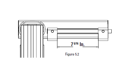
5.2 Rear Upright and Base Clamp Assembly
The rear uprights should sit as far towards the tailgate as possible without the base hanging off the back of the bed rail, while maximizing the distance between the clamps (Figure 5.2)
6. Place the rear uprights on top of the rounded shims (Item 8) making sure that the rubber shims are completely under the bases.
7. With the second pair of uprights now on the truck they must be secured using two of the previously assembled (Step 4) clamps (2 per upright). When positioning the clamps make sure they are spaced at least 7 5/16 inches apart. Any less of a distance will reduce the load capacity of the rack. You may adjust the position of the rack on the bed to ensure that this distance can be achieved
8. Repeat Steps 3-5 on the rear rack.
9. Finally with the uprights secured you now want to take a measuring tape and center your crossbars. Once centered use your 7/32” Allen Wrench (or 7/32” Allen Drive Bit) to fully secure your crossbars. Torque the BHCS to 27 ft-lbs.
5.2.1 When tightening the 3/8” flat head cap screws ensure that the allen key is fully seated in the bolt so that it will not strip