FREE 1 to 3-Day Delivery on Orders $119+ Details
How to Install Tuff Country 4.5 in. Lift Kit w/ SX6000 Shocks on your F-150
Installation Time
3 hours
Tools Required
- Cut off wheel
- Sawzall
- Torsion bar puller (Part # 7826 / LSP code: 765 005 15)
- Torque wrench
- Standard socket set
- Standard wrench set
- Metric socket set
- Metric wrench set
- Tape measure
- Hydraulic floor jacks
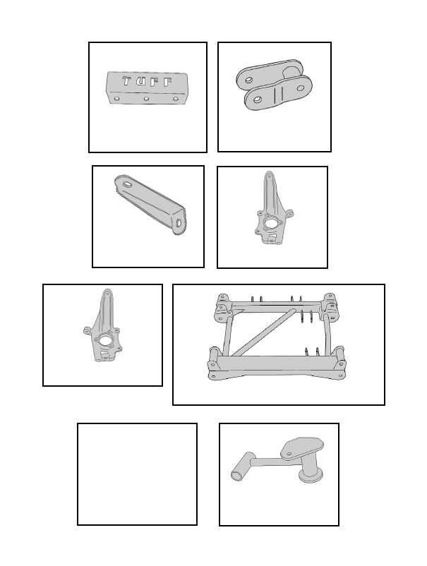
Parts contained in Box 1 of 3
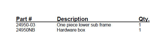
Parts contained in Box 2 of 3
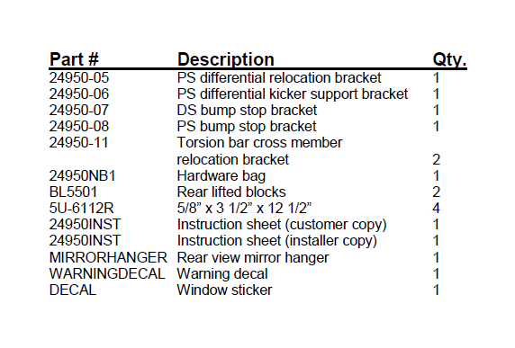
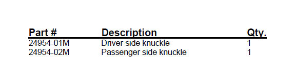
Parts contained in Box 3 of 3
Congratulations on your selection to purchase a Tuff Country EZ-Ride Suspension System. We at Tuff Country are proud to offer a high quality product at the industries most competitive pricing. Thank you for your confidence in us, and our product.
Before installation begins, it is the customers/ installers responsibility to make sure that all parts are on hand. If any parts are missing, please feel free to call one of our customer service representative @ (800) 288-2190.
Tuff Country EZ-Ride Suspension highly recommends that a qualified and or certified installer performs this installation.
If you desire to return your vehicle to stock, it is the customers responsibility to save all stock hardware.
Make sure to use thread locker or lock tite on all new and stock hardware associated with this installation.
Important customer information
This vehicles reaction and handling characteristics may differ from standard cars and/or trucks. Modifications to improve and/or enhance off road performance may raise the intended center of gravity. Extreme caution must be utilized when encountering driving conditions which may cause vehicle imbalance or loss of control. DRIVE SAFELY! Avoid abrupt maneuvers, such as sudden sharp turns which could cause a roll over, resulting in serious injury or death.
It is the customers responsibility to make sure that a re-torque is performed on all hardware associated with this suspension system after the first 100 miles of installation. It is also the customers responsibility to do a complete re-torque after every 3000 miles or after every off road use.
After the original installation, Tuff Country EZ-Ride Suspension also recommends having the alignment check every 6 months to ensure proper tracking, proper wear on tires and front end components. Tuff Country EZ-Ride Suspension take no responsibility for abuse, improper installation or improper suspension maintenance.
It is the responsibility of the customer or the installer to wear safety glasses at all times when performing this installation.
It is the customers/installers responsibility to read and understand all steps before installation begins. OEM manual should be used as a reference guide.
It is the responsibility of the installers to make sure that the customer receives a copy of the instruction sheet along with the rear view mirror hanger and warning decal. All of this information is packaged in box 2 of 3 is a clear bag with a “Customer” sticker attached to it.
The Tuff Country EZ-Ride Suspension product safety label that is included in your kit box must be installed inside the cab in plain view of all occupants.
Important information that needs to be read and understood before installation begins;
Tuff Country EZ-Ride Suspension recommends using a medium off set tire and wheel combination. The stock wheels will not work in combination with the new knuckle design.
After the installation is complete, a front end alignment is required. Also, some vehicles may need to have an exhaust modification performed.
Tuff Country EZ-Ride Suspension recommends running a 35” x 12.50” tire for maximum tire clearance. This tire size in not 100% accurate due to variations in wheel width, wheel off set, tire diameters and driving habits.
If any tire larger than a 35 x 12.50 is installed in conjunction with part # 24950, the Tuff Country warranty will be VOID.
For a list of all parts, please refer to the parts description page, at the end of the installation manual.
Before installation begins, Tuff Country EZ-Ride Suspension highly recommends that the installer performs a test drive on the vehicle. During the test drive, check to see if there are any uncommon sounds or vibrations. If uncommon sounds or vibrations occur on the test drive, uncommon sounds or vibrations will be enhanced once the suspension system has been installed. Tuff Country EZ-Ride Suspension highly recommends notifying the customer prior to installation to inform the customer of these issues if they exist.
New longer front and rear shocks are needed after this suspension system has been installed and the front and rear shocks need to be ordered as a separate part #. If you have not already ordered your front and rear shocks, please feel free to contact Tuff Country or your local Tuff Country dealer and order your front and rear shocks.
Once the installation is complete and a front end alignment has been performed, test drive the vehicle to see if there are any front drive line vibrations. If front drive line vibration occurs, take the front drive line to a drive line shop and have the front drive line re-balanced.
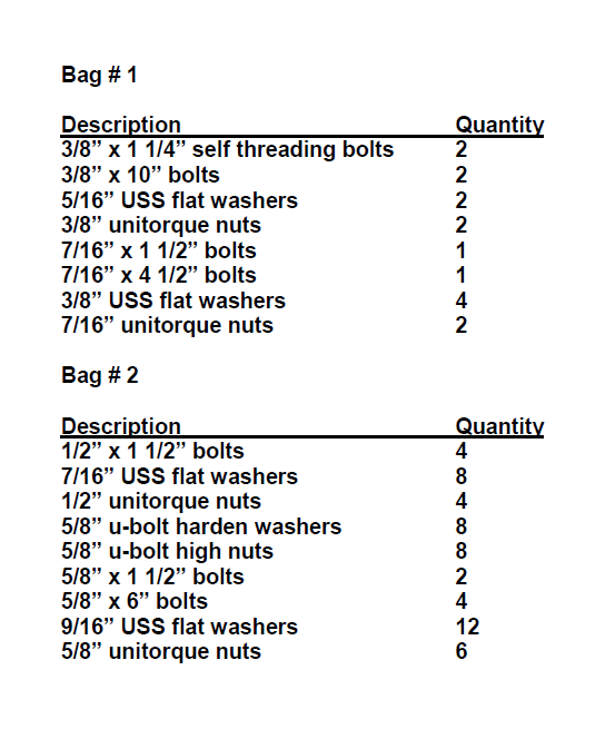
Hardware bag 24950NB1 includes:
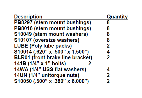
Hardware bag 24950NB includes:
Special note: Before installation begins, it is the customers/installers responsibility to make sure that all parts are on hand. If any parts are missing, please feel free to call one of our customer service representatives @ (801) 280-2777.
Special post installation procedure: Tuff Country EZRide Suspension highly recommends adding a minimum of 1 pint, but no more that 1 1/2 pints, of proper front differential fluid into the front differential. To achieve this, you may have to fill the differential with it on its side or you may have to insert the fluid through the vend tube opening. On occasion, the customer may find burping of fluid coming out of the front vent tube.
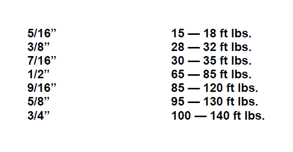
Torque settings:
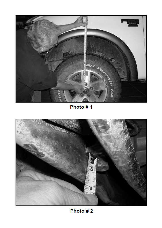
Before installation begins, measure from the center of the hub, to the bottom of the fender well, and record measurements below.
Photo # 1 / driver side front shown
Pre installation measurements:
Driver side front:______________________________
Passenger side front:__________________________
Driver side rear:______________________________
Passenger side rear:__________________________
At the end of the installation take the same measurements and compare to the pre-installation measurements.
Post installation measurements:
Driver side front:______________________________
Passenger side front:__________________________
Driver side rear:______________________________
Passenger side rear:__________________________
Please follow instructions carefully:
Front end installation:
1. To begin installation, block the rear tires of the vehicle so that the vehicle is stable and can’t roll backwards. Safely lift the front of the vehicle and support the frame with a pair of jack stands. Place a jack stand on both the driver and passenger side. Next, remove the wheels and tires from both sides.
2. Working on the driver side, remove the stock hardware on the top of the stock shock. The upper stock hardware may be discarded. Remove the stock hardware on the lower shock mount and save hardware for later reinstallation. The stock shock may be discarded. Special note: New longer front shocks are needed, if you have not already ordered shocks, please contact Tuff Country or your local Tuff Country dealer and order the proper shocks. Tuff Country recommends using a 23” fully extended nitrogen gas shock. Repeat procedure on the passenger side.
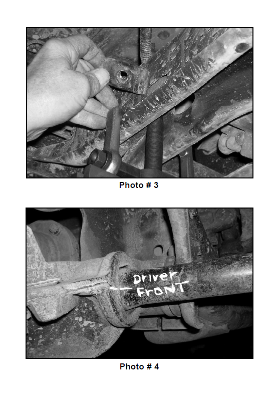
3. Measure exposed threads on the torsion bar adjustment bolt and record measurement here for a later reference.
Record driver side measurement here:______________
Record passenger side measurement here:__________
Photo # 2
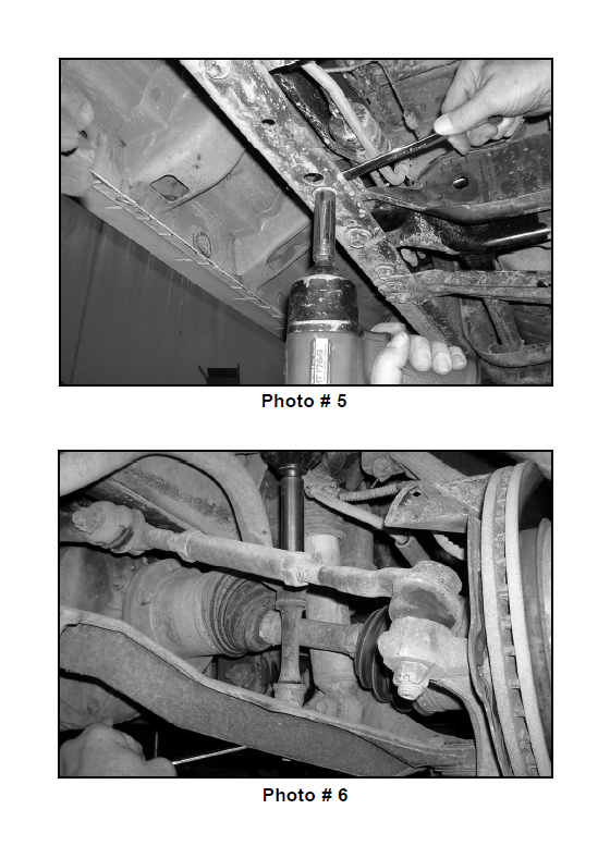
4. Working on the driver side, attach the torsion bar removing tool to the stock torsion bar cross member, making sure that the unloading bolt in the center of the torsion bar removing tool is in the small divot of the stock torsion bar key. Adjust the torsion bar key up high enough so that the stock small metal adjusting block and bolt can be removed. Set the stock torsion bar block and bolt aside for later re-installation. Repeat procedure on passenger side.
Photo # 3
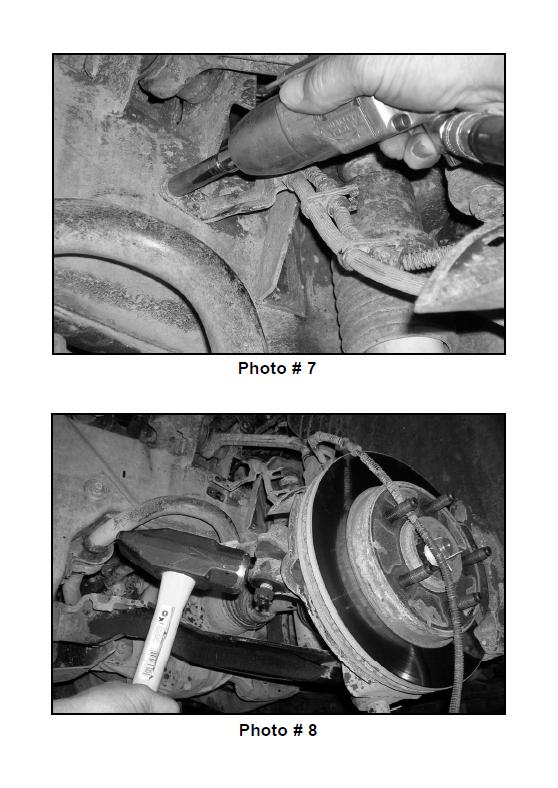
5. Mark both torsion bars before removal so that they can be re-installed back into the same location. Example: Driver vs. Passenger and front vs. rear. Tap the stock torsion bars forward until the stock torsion bar cross member can be removed. Once you tap the stock torsion bar out of the stock torsion bar cross member, the stock torsion bar key will fall out. Set the stock torsion bar key aside for later re-installation. Slide the torsion bar forward in the stock lower control arm far enough so that the stock torsion bar cross member can be removed. Special note: Take special care not to push the torsion bar into the stock CV axle, if this happens, damage may occur to the stock CV axle. Repeat procedure on the passenger side.
Photo # 4
6. Working on the driver side, remove the stock bolts that connects the stock torsion bar cross member to the stock mounting point. Save the stock hardware for later reinstallation. Repeat procedure on the passenger side. Remove the stock torsion bar cross member from the stock location and set aside for later re-installation.
Photo # 5
7. Working on the driver side, slide the stock torsion bar out of the stock rear lower control arm and set aside for later re-installation. Repeat procedure on passenger side.
8. Working on the driver side, remove the stock sway bar end link from the stock sway bar and the stock lower control arm and discard the stock end link and all the stock hardware. Repeat procedure on the passenger side.
Photo # 6
9. Working on the driver side, remove the stock bolt that connects the stock brake line bracket to the stock frame rail. Save the stock hardware for later re-installation.
Photo # 7
10. Working on the driver side, locate the ABS line quick disconnect located above the stock upper control arm. Disconnect the ABS lines from each other. Also disconnect the ABS line from any other mounting points. Set the stock hardware aside for later re-installation. Let ABS line hang. Special note: If the vehicle that you are working on is not equipped with front ABS, please skip this step.
11. Working on the driver side, loosen the stock nut that connects the stock outer tie rod ball joint to the stock steering knuckle. Do not remove the stock nut completely. Carefully break the stock taper on the stock outer tie rod ball joint. Special note: Slight tapping of the stock knuckle will break the stock taper. Take special care not to rip or tear the stock outer tie rod ball joint dust boot.
Photo # 8
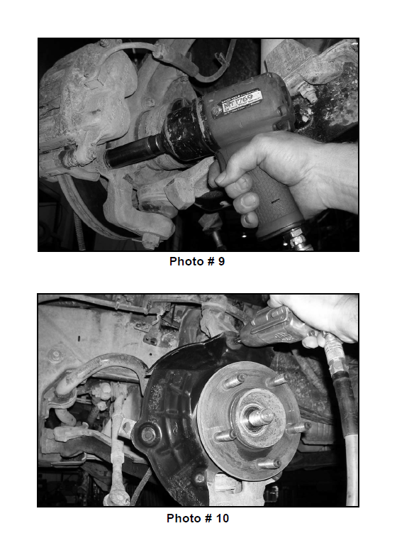
12. Working on the driver side, remove the (2) stock bolts that connect the stock brake caliper to the stock knuckle. Save the stock hardware for later re-installation. Using a bungee cord, carefully tie the stock brake caliper up and out of the way in the fender well. Special note: Take special care not to kink or over extend the stock brake line.
Photo # 9
13. Working on the driver side, remove the stock rotor and set aside for later re-installation.
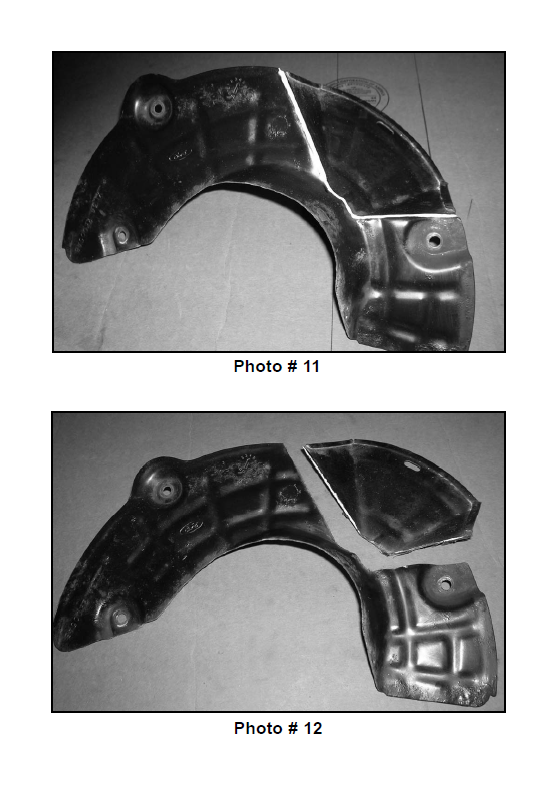
14. Working on the driver side, remove the stock dust shield from the stock hub assembly. Set the stock dust shield hardware aside for later re-installation. The stock dust shield needs to be trimmed. Refer to photo # 11 and 12 for proper cut line. Using a die grinder, carefully cut along the cut line. Once trimming has been performed, set the modified stock dust shield aside for later reinstallation. Special note: Make sure to wear safety glasses when performing this step.
Photo # 10 / removal of dust shield
Photo # 11 / pre cut view
Photo # 12 / post cut view
15. Working on the driver side, remove the stock cotter pin that holds the stock cap and nut to the stock axle and hub assembly. Save the stock nut and cotter pin for later re-installation.
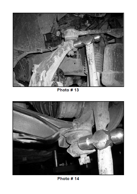
16. Working on the driver side, remove the stock cotter pin on the stock upper control arm ball joint. Set the stock cotter pin aside for later re-installation. Loosen the stock nut that connects the stock upper control arm ball joint to the stock steering knuckle. Do not remove the stock nut completely. Carefully break the stock taper on the stock upper control arm ball joint. Special note: Slight tapping of the stock knuckle will break the stock taper. Take special care not to rip or tear the stock ball joint dust boot.
Photo # 13
17. Working on the driver side, remove the stock cotter pin on the stock lower control arm ball joint. Set the stock cotter pin aside for later re-installation. Loosen the stock nut that connects the stock lower control arm ball joint to the stock steering knuckle. Do not remove the stock nut completely. Carefully break the stock taper on the stock lower control arm ball joint. Special Note: Take special care not to rip or tear the stock ball joint dust boot.
Photo # 14
18. Working on the driver side, move back to the stock nuts holding the upper control arm ball joint and the lower control arm ball joint to the stock steering knuckle and remove completely. Save the stock hardware for later reinstallation.
19. Working on the driver side, remove the stock axle from the hub assembly. Special note: Take special care not to damage the stock threads on the stock axle.
20. Carefully remove the stock hub assembly and the stock steering knuckle from the stock location.
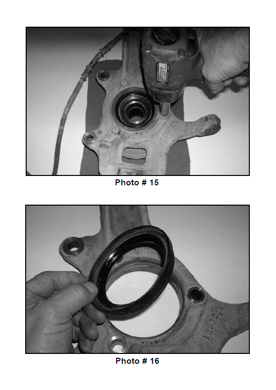
21. Working on the driver side stock hub assembly, remove the (3) stock bolts that connect the stock hub assembly to the stock steering knuckle. Set the (3) stock bolts aside for later re-installation. Carefully separate the stock hub assembly from the stock steering knuckle. Carefully remove the stock seal from the stock steering knuckle. Set the stock seal aside for later re-installation. A new steering knuckle is used, the stock steering knuckle can be discarded.
Photo # 15 / hub assembly bolts
Photo # 16 / seal removal
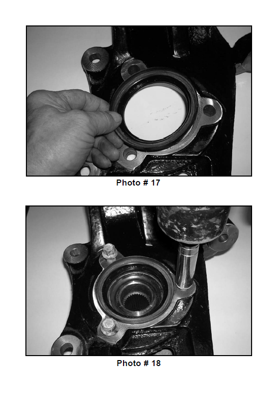
22. Locate the new driver side steering knuckle and the stock seal that was removed from step # 21. Install the stock seal into the new driver side steering knuckle.
Photo # 17
23. Using the stock hardware that was removed from step # 21, secure the new driver side steering knuckle to the stock hub assembly. Torque to 92 ft lbs. Special note: Make sure to use thread locker or lock tite.
Photo # 18
24. Set the new driver side steering knuckle and the stock hub assembly aside for later re-installation.
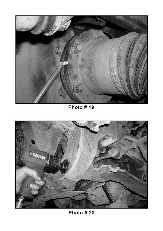
25. Working on the driver side, scribe a mark on the CV plate and another directly across to the stock differential, this will allow you to re-install the stock CV back into the stock location at a later step.
Photo # 19
26. Working on the driver side, unbolt and remove the (6) stock bolts holding the inner CV to the stock differential. Save the stock hardware for later re-installation. Set the stock axle aside for later re-installation.
27. Working on the driver side, remove the stock hardware that connects the stock lower control arm into the stock front and rear lower control arm location. Set the stock lower control arm and the stock hardware aside for later re-installation.
Photo # 20 / driver side front shown
28. Repeat step’s 9 - 27 on the passenger side.
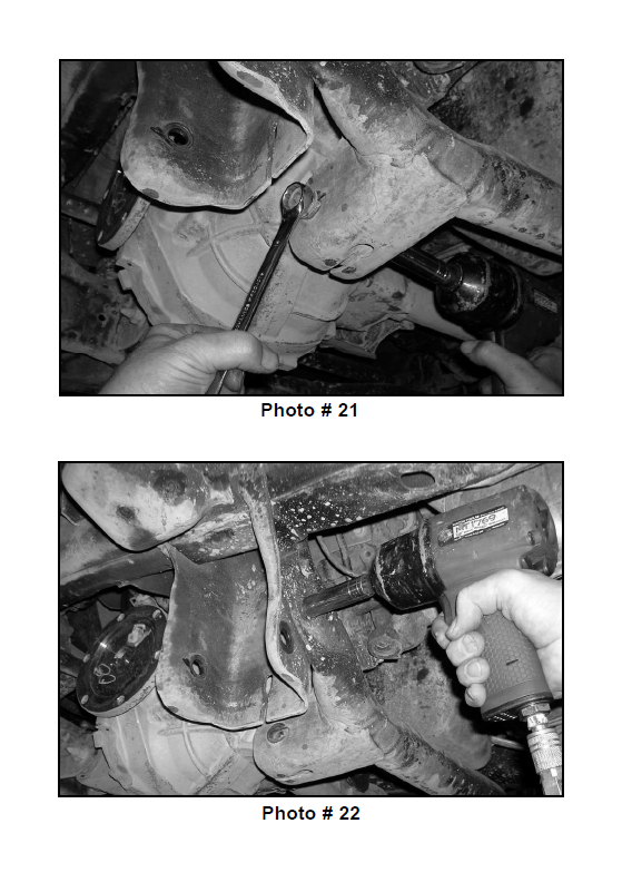
29. Working on the driver side, remove the stock bolt that connects the lower rear portion of the front differential to the stock rear cross member. Save the stock hardware for later re-installation.
Photo # 21
30. Working on the driver side, remove the (2) stock bolts that connect the stock rear cross member to the stock rear lower control arm drop bracket. Repeat procedure on the passenger side. The stock rear cross member and hardware may be discarded.
Photo # 22 / driver side shown
31. Locate the new one piece lower sub frame and the stock hardware that was removed from step # 27. Install the new one piece lower sub frame into the stock front and rear lower control arm pockets. Secure the front and rear portion of the new one piece sub frame into the stock front and rear lower control arm pockets using the stock bolts and hardware. Special note: Make sure to use thread locker or lock tite. Do not tighten at this point.
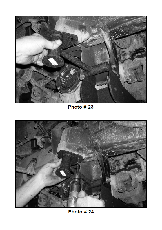
32. Locate the driver and passenger side bump stop brackets. Working on the driver side rear lower control arm pocket, remove the stock bolt and hardware that connects the new one piece lower sub frame into the stock rear lower control arm pocket. Save the stock hardware for later re-installation. Install the new driver side bump stop spacer into the rear pocket on the new one piece lower sub frame located in the stock rear lower control arm pocket. Secure using the stock bolt and hardware that was removed earlier in this step. Do not tighten at this point. Repeat procedure on the passenger side.
Photo # 23
33. Working on the driver side, hold the new driver side bump stop bracket flush with the stock bump stop location. Using the new driver side bump stop bracket as a guide, carefully drill a 5/16” hole into the stock bump stop location. Repeat procedure on the passenger side.
Photo # 24
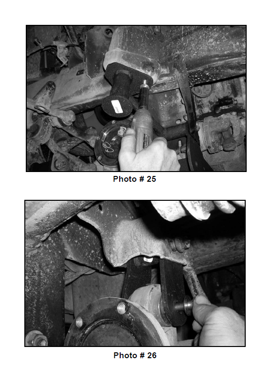
34. Locate (2) 3/8” x 1 1/4” self threading bolt and (2) 5/16” USS flat washers from hardware bag 24950NB-1. Secure the new driver side bump stop spacer to the bottom side of the bump stop location using the new 3/8” x 1 1/4” self threading bolt and hardware. Torque to 34 ft. lbs. Special note: Make sure to use thread locker or lock tite. Repeat procedure on the passenger side.
Photo # 25
35. Secure the front differential with a pair of hydraulic floor jacks. Place one jack stand on the driver side and one on the passenger side.
36. Working on the driver side, remove the stock bolt that holds the upper portion of the stock front differential into the stock location. Save the stock hardware for later reinstallation. Repeat procedure on the passenger side.
37. Carefully lower down on both jack stands at the same time until the front and rear portion of the driver side differential seat into the new pockets on the front and rear portion of the new one piece lower sub frame.
38. Locate the stock front differential rear hardware that was removed in step # 29. Also, locate the stock front differential front hardware that was removed from step # 36. Secure the front and rear portion of the stock differential into the new lower one piece sub frame using the stock hardware Special note: Make sure to use thread locker or lock tite. Do not tighten at this point.
39. Locate the passenger side differential relocation bracket, the passenger side kicker support bracket, the passenger side stock hardware that was removed from step # 36, (1) 7/16” x 4 1/2” bolt, (1) 7/16” x 1 1/2” bolt, (4) 3/8” USS flat washers and (2) 7/16” unitorque nuts from hardware bag 24950NB-1. Working on the passenger side, install the new passenger side differential drop bracket into the stock location and secure using the stock hardware. Special note: The new passenger side differential drop bracket has a bend on one of the legs of the bracket. This leg of the bracket needs to be installed towards the rear of the vehicle. Make sure to use thread locker or lock tite. Do not tighten at this point.
40. Raise up on the hydraulic floor jack until the passenger side of the front differential seats properly into the newly installed passenger side differential drop bracket. Also at this time install the passenger side kicker support bracket. Secure the passenger side kicker support bracket, the newly installed passenger side differential drop bracket using the new 7/16” x 4 1/2” bolt and hardware. Special note: Make sure to use thread locker or lock tite. Do not tighten at this point.
Photo # 26
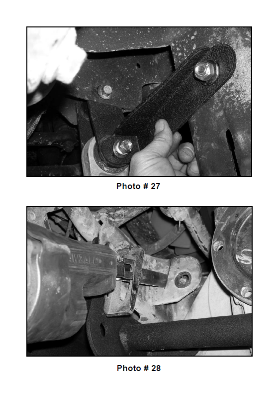
41. Working on the passenger side, install the rear portion of the passenger side kicker support bracket to the inner part of the passenger side stock rear lower control arm pocket. Secure using the new 7/16” x 1 1/2” bolt and hardware. Special Note: Make sure to use thread locker or lock tite. Do not tighten at this point.
Photo # 27
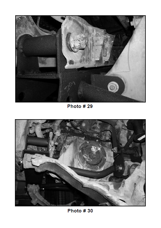
42. Working on the driver side, carefully cut off the stock front differential mounting tabs. Special note: Tuff Country recommends not using a cutting torch when performing step # 41. Once you have cut of the stock front differential tabs, clean and dress any exposed metal and remove the 2 hydraulic floor jacks from under the front differential.
Photo # 28 / cutting view
Photo # 29 / post cut view
43. Move back to all new and stock hardware associated with the new lower one piece sub frame, the new and stock hardware associated with the front differential, the front passenger side differential drop bracket and the passenger side kicker support and torque to proper specs. Refer to the torque setting sheet at the end of the installation manual.
44. Locate the stock driver and passenger side lower control arms that were removed in step # 27. Locate (4) 5/8” x 6” bolts, (8) 9/16” USS flat washers and (4) 5/8” unitorque nuts from hardware bag 24950NB-2. Working on the driver side, install the stock lower control arm into the front and rear pockets of the new one piece lower sub frame using the new 5/8” x 6” bolts and hardware. Special note: Make sure to use thread locker or lock tite. Do not tighten at this point. Repeat procedure on the passenger side.
Photo # 30 / driver side shown
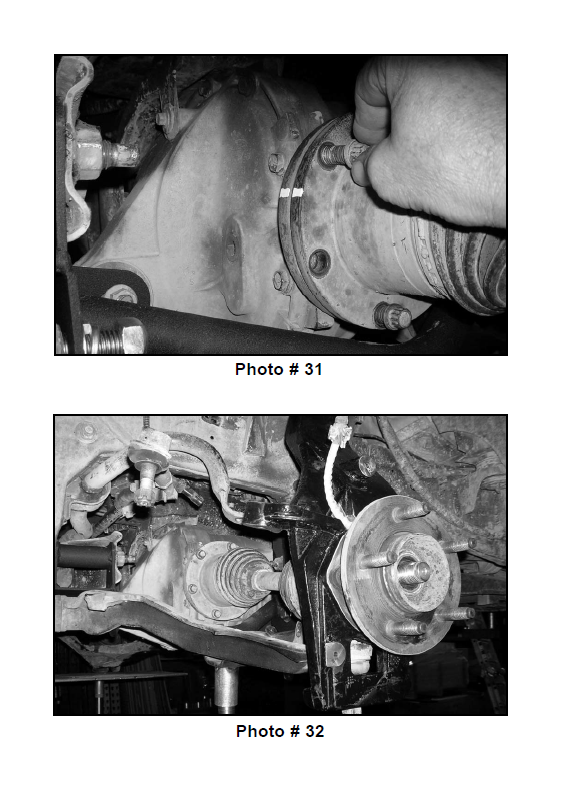
45. Locate the stock driver and passenger side axles and the stock hardware that was removed in step # 26. Working on the driver side install the driver side axle to the stock front differential and secure using the stock hardware. Torque to 65 ft lbs. Special note: Make sure to use thread locker or lock tite. Also, make sure that the stock axle is re-installed back into the stock location on the stock front differential. Refer to the scribe mark that was made in step # 25. Repeat procedure on the passenger side.
Photo # 31
46. Locate the new driver side steering knuckle, the stock hardware for the upper control arm ball joint and the lower control arm ball joint that was removed from step # 18. Using the stock hardware, secure the new driver side steering knuckle and stock hub assembly to the stock upper control arm ball joint and the stock lower control arm ball joint. Torque the stock hardware on the upper and lower ball joints to 85 ft lbs. Special note: When installing the new driver side spindle, make sure that the stock brake line is located towards the inside of the vehicle. Make sure to use thread locker or lock tite. Also when performing this step, slide the stock axle into the stock hub assembly location. Repeat procedure on the passenger side using the passenger side steering knuckle.
Photo # 32
47. Locate the stock hardware that connects the stock front axle to the stock hub assembly that was removed in step # 15. Working on the driver side, secure the stock front axle to the hub assembly using the stock hardware. Torque to 112 ft. lbs. Make sure to use thread locker or lock tite. Make sure to re-install the stock cap and cotter pin. Repeat procedure on the passenger side.
48. Working on the driver side, secure the stock ABS line to the new steering knuckle using the stock hardware that was removed from step # 10.
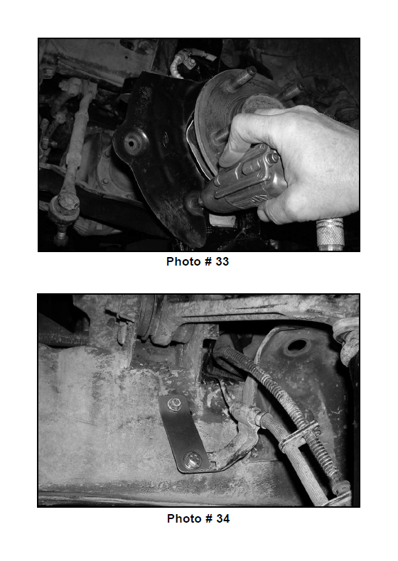
49. Locate the modified stock dust shield and hardware that was removed from step # 14. Working on the driver side, install the modified dust shield to the newly installed steering knuckle using the stock hardware. Special note: Make sure to not over tighten. Repeat procedure on the passenger side.
Photo # 33
50. Locate the stock rotors that were removed from step # 13. Working on the driver side, install the stock rotors into the stock location. Repeat procedure on the passenger side.
51. Locate the stock brake caliper hardware that was removed in step # 12. Working on the driver side, reinstall the stock brake caliper to the new spindle and secure using the stock hardware. Torque to 76 ft. lbs. Special note: Make sure to use thread locker or lock tite. Repeat procedure on the passenger side.
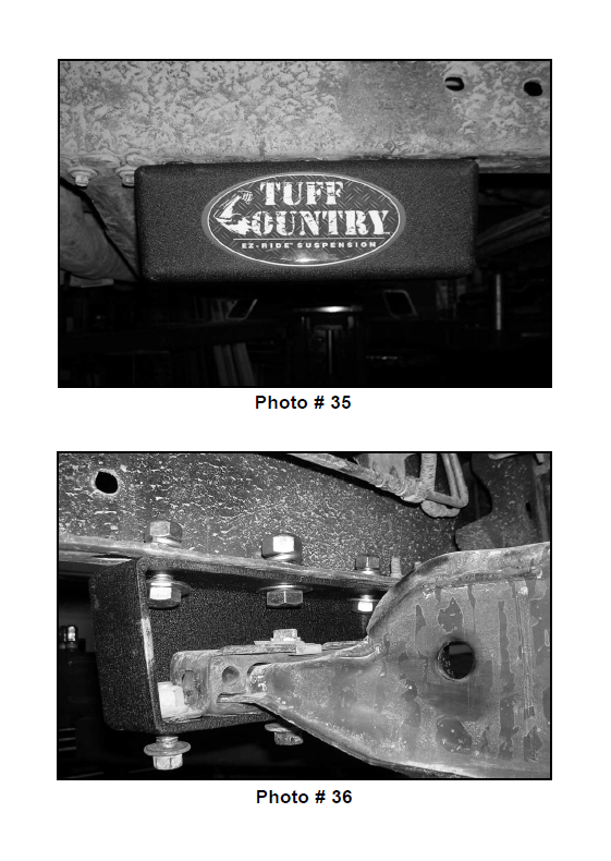
52. Locate (2) BLR01 from hardware bag 24950NB1. Also, locate the stock brake line hardware that was removed in step # 9. Working on the driver side, install the new brake line bracket to the stock frame rail and secure using the stock hardware. Do not tighten at this point. Repeat procedure on the passenger side.
53. Locate (2) 1/4” x 1” bolts, (4) 1/4” USS flat washers and (2) 1/4” unitorque nuts from hardware bag 24950NB1. Working on the driver side, install the stock brake line bracket to the newly installed brake line relocation bracket and secure using the new 1/4” x 1” bolt and hardware. Torque the stock and new hardware to 12 ft lbs. Repeat procedure on the passenger side
Photo # 34
54. Locate the stock outer tie rod hardware that was removed in step # 11. Working on the driver side, secure the stock outer tie rod to the newly installed knuckle and torque the outer tie rod ball joint hardware to 68 ft. lbs. Special note: Make sure to use thread locker or lock tite. Repeat procedure on the passenger side.
If the vehicle that you are working on has a transmission oil pan that measures 13” x 13”, please follow steps # 55 — 57
If the vehicle that you are working on has a transmission oil pan that measures 13” x 23”, please follow steps # 58 — 60
55. Locate (2) new torsion bar drop blocks, (4) 1/2” x 1 1/2” bolts, (8) 7/16” USS flat washers, (4) 1/2” unitorque nuts, (2) 5/8” x 1 1/2” bolts, (4) 9/16” flat washers and (2) 5/8” unitorque nuts from hardware bag 24950NB-2. Working on the driver side, install the new torsion bar drop block into the stock location on the bottom side of the stock frame rail and secure using the new 1/2” x 1 1/2” bolts and hardware into the (2) outer holes. Do not tighten at this point. Install the new 5/8” x 1 1/2” bolt and hardware into the center hole. Do not tighten at this point. Make sure to use thread locker or lock tite. Repeat procedure on the passenger side.
Photo # 35
56. Locate the stock driver and passenger side torsion bars that were removed from step # 7. Working on the driver side, slide the stock torsion bar into the stock lower control arm and let hang. Special note: Make sure to re-install the stock torsion bar back into the stock location. Example: Driver vs. Passenger and front vs. rear. Take special care not to push the torsion bar into the stock CV axle, if this happens, damage may occur to the stock CV axle. Repeat procedure on the passenger side.
57. Locate the stock torsion bar cross member and the stock hardware that was removed in step # 6. Working on the driver side, install the stock torsion bar cross member to the newly installed torsion bar drop bracket and secure using the stock hardware. Torque to 75 ft lbs. Make sure to use thread locker or lock tite. Special note: Install the stock torsion bar cross member to the inside of the new torsion bar drop blocks. Repeat procedure on the passenger side. Move back to the new hardware that was installed in step # 55. Torque the 1/2” hardware to 85 ft lbs. Torque the 5/8” hardware to 95 ft lbs.
Photo # 36
58. Locate (2) new torsion bar drop blocks, (4) 1/2” x 1 1/2” bolts, (8) 7/16” USS flat washers, (4) 1/2” unitorque nuts, (2) 5/8” x 1 1/2” bolts, (4) 9/16” flat washers and (2) 5/8” unitorque nuts from hardware bag 24950NB-2. Working on the driver side, install the new torsion bar drop block into the stock location on the bottom side of the stock frame rail and secure using the new 1/2” x 1 1/2” bolts and hardware into the (2) outer holes. Do not tighten at this point. Install the new 5/8” x 1 1/2” bolt and hardware into the center hole. Do not tighten at this point. Make sure to use thread locker or lock tite. Repeat procedure on the passenger side.
Photo # 35
59. Locate the stock driver and passenger side torsion bars that were removed from step # 7. Working on the driver side, slide the stock torsion bar into the stock lower control arm and let hang. Special note: Make sure to re-install the stock torsion bar back into the stock location. Example: Driver vs. Passenger and front vs. rear. Take special care not to push the torsion bar into the stock CV axle, if this happens, damage may occur to the stock CV axle. Repeat procedure on the passenger side.
60. Locate the stock torsion bar cross member and the stock hardware that was removed in step # 8. Working on the driver side, install the stock torsion bar cross member to the newly installed torsion bar drop bracket and secure using the stock hardware. Torque to 75 ft lbs. Make sure to use thread locker or lock tite. Special Note: Install the stock torsion bar cross member to the bottom side of the new torsion bar drop blocks. Repeat procedure on the passenger side. Move back to the new hardware that was installed in step # 58. Torque the 1/2” hardware to 85 ft lbs. Torque the 5/8” hardware to 95 ft lbs.
61. Locate the stock driver and passenger side torsion bar key’s that were removed from step # 6. Working on the driver side, install the stock torsion bar key back into the stock torsion bar cross member. Holding the stock torsion bar key into the stock location, slide the driver side torsion bar into the stock torsion bar key. Repeat procedure on the passenger side. Special note: Make sure that the torsion bar is installed back into the torsion bar key just as it was removed.
62. Locate the small metal adjusting blocks and bolts that were removed from step # 4. Working on the driver side, attach the torsion bar removing tool, making sure that the unloading bolt in the center tool is in the small divot of the torsion bar key. Adjust the torsion bar key up high enough so that the small metal adjusting block and stock bolt can be re-installed, Refer back to step # 3 and adjust the stock bolt to the stock location. Repeat procedure on passenger side. Remove the torsion bar removing tool.
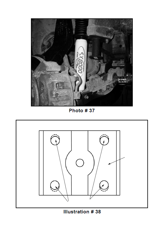
63. Locate the new front shocks. Special note: New longer front shocks are needed, if you have not already ordered shocks, please contact Tuff Country or your local Tuff Country dealer and order the proper shocks. Tuff Country recommends using a 23” fully extended nitrogen gas shock. Locate (2) S10014, (4) PB8297 upper shock bushings and (4) S10107 upper shock washers from hardware bag 24950NB1. Working on the new shocks, install the new lower shock bushing into the lower eyelet and install the new S10014 shock sleeves into the previously installed bushings. Special note: Make sure to use a lithium or moly base grease prior to inserting the new lower shock bushings and sleeves into the new lower shock eyelet. This will increase the life of the bushing as well as prevent squeaking. Working on the driver side, install the new shock into the stock location using the stock hardware on the bottom mount that was removed in step # 2 and the new hardware on the top mount. Repeat procedure on the passenger side. Special note: Make sure to use the new upper bushings and upper shock washers. Torque the lower shock mount to 65 ft lbs. and the upper hardware to 22 ft lbs. Repeat on passenger side. Special note: Tuff Country EZ-Ride Suspension highly recommends that the shocks are installed with shock boots. If shock boots are not installed, damaged might occur to the piston of the new shock.
Photo # 37
64. Install the tires and wheels and carefully lower the vehicle to the ground.
65. There is still a couple of steps that need to be completed on the front end but these steps will not be completed until the rear end installation is completed and the weight of the vehicle is on the ground. These steps include: the installation of the front sway bar end links and the tightening of the new hardware that connects the lower control arms to the newly installed sub frame.
Rear end installation:
66. To begin installation, block the front tires of the vehicle so that the vehicle is stable and can’t roll forward. Safely lift the rear of the vehicle and support the frame with a pair of jack stands. Place a jack stand on both the driver and passenger side. Next, remove the wheels and tires from both sides.
67. Position a pair of hydraulic floor jacks under the rear axle. Place one jack stand on the driver side and one on the passenger side. Raise up on both hydraulic floor jacks at the same time until they make contact with the rear axle. Special note: You may need to remove the plastic clip that holds the E-brake cable together.
68. Working on the driver side, remove the stock hardware on the top of the stock shock. The upper stock hardware may be discarded. Remove the stock hardware on the lower shock mount and save hardware for later reinstallation. The stock shock may be discarded. Special note: New longer front shocks are needed, if you have not already ordered shocks, please contact Tuff Country or your local Tuff Country dealer and order the proper shocks. Tuff Country recommends using a 30” fully extended nitrogen gas shock. Repeat procedure on the passenger side.
69. Working on the driver side, remove the stock rear ubolts from the stock location. The stock u-bolts and hardware may be discarded. Set the stock upper u-bolt plate aside for later re-installation. Repeat procedure on passenger side.
70. Working on the driver side upper u-bolt plate, open each hole 1/8” to the outside of the u-bolt plate. See Illustration # 38 for proper placement. Set the upper ubolt plate a side for later re-installation. Repeat procedure on the passenger side.
Illustration # 38
71. Lower down on both hydraulic floor jacks at the same time until the stock springs separate from the stock rear axle. Lower down approximately 4”. Special note: Make sure not to over extended any brake lines or hoses when lowering the stock rear axle.
72. Working on the driver side, remove the stock block from the stock location and discard. Repeat procedure on the passenger side.
73. Locate (2) new 5.5” lifted rear blocks. Working on the driver side, install (1) new 5.5” lifted rear block between the stock rear axle and the stock spring assembly. Special note: The new 5.5” lifted block has a taper to it, the small end of the new block needs to be installed towards the front of the vehicle. Repeat procedure on passenger side.
Illustration # 39
74. Raise up on both hydraulic floor jacks at the same time until the driver and passenger side stock spring assembly seats flush with newly installed 5.5” block.
75. Locate (4) new 5/8” x 3 1/2” x 12 1/2” round u-bolts. Locate (8) 5/8” u-bolt high nuts and (8) 5/8” u-bolt washers from hardware bag 24950NB-2. Also, locate the modified stock upper u-bolt plates. Working on the driver side, install the new 5/8” x 3 1/2” x 12 1/2” round u-bolts into the stock location and secure using the new 5/8” high nuts and washers. Torque to 135 ft lbs. With a suitable cutting tool, cut off the extra thread from the new u-bolts. Repeat procedure on passenger side.
Illustration # 39
76. Locate the new rear shocks. Special note: New longer front shocks are needed, if you have not already ordered shocks, please contact Tuff Country or your local Tuff Country dealer and order the proper shocks. Tuff Country recommends using a 30” fully extended nitrogen gas shock. Locate (2) S10014, (4) PB8297 upper shock bushings and (4) S10107 upper shock washers from hardware bag 24950NB1. Working on the new shocks, install the new lower shock bushing into the lower eyelet and install the new S10014 shock sleeves into the previously installed bushings. Special note: Make sure to use a lithium or moly base grease prior to inserting the new lower shock bushings and sleeves into the new lower shock eyelet. This will increase the life of the bushing as well as prevent squeaking. Working on the driver side, install the new shock into the stock location using the stock hardware on the bottom mount that was removed in step # 68 and the new hardware on the top mount. Repeat procedure on the passenger side. Special note: Make sure to use the new upper bushings and upper shock washers. Torque the lower shock mount to 65 ft lbs. and the upper hardware to 22 ft lbs. Repeat on passenger side. Special note: Tuff Country EZ-Ride Suspension highly recommends that the shocks are installed with shock boots. If shock boots are not installed, damaged might occur to the piston of the new shock.
77. Carefully remove both hydraulic floor jacks from under the vehicle.
78. Install the tires and wheels and carefully lower the vehicle to the ground.
Step # 79 and # 80 needs to be performed with the weight of the vehicle on the ground.
79. Working on the driver side, move back to the new 5/8” hardware attaching the stock lower control arms to the newly installed one piece lower sub frame and torque to 125 ft lbs. Repeat procedure on the passenger side.
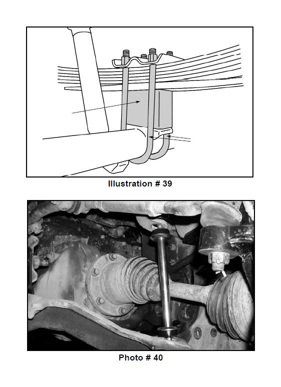
80. Locate (2) 3/8” x 10” bolts and (2) 3/8” unitorque nuts from hardware bag 24950NB-1. Also, locate (2) sway bar end links, (8) sway bar end link bushings and (8) sway bar end link washers from hardware bag 24950NB1. Working on the driver side, install the new sway bar end link and hardware into the stock location. Torque to 32 ft lbs. Make sure to use thread locker or lock tite. Repeat procedure on the passenger side.
Photo # 40
81. Check and double check to make sure that all steps were performed properly and then check again. Check and make sure that all new and stock hardware has been torqued to proper torque specification. Refer to the torque specification at the beginning of the installation manual.
82. Take the vehicle directly to an alignment shop for a proper front end alignment.
If you have any questions regarding the installation, please contact the technical department @ Tuff Country. (801) 280-2777
Congratulations, installation complete. Check and double check to make sure that all steps were performed properly. Check torque settings to make sure that all stock and new hardware has been torqued to proper torque specifications
Also refer to the Vehicle owners manual for proper torque specifications on any stock hardware.
Special post installation procedure: Tuff Country EZ-Ride Suspension highly recommends adding a minimum of 1 pint, but no more that 1 1/2 pints, of proper front differential fluid into the front differential. To achieve this, you may have to fill the differential with it on its side or you may have to insert the fluid through the vent tube opening. On occasion, the customer may find burping of fluid coming out of the front vent tube.