 FREE 1 to 3-Day Delivery on Orders $119+ Details
How to Install Zone Offroad 2 in. Suspension Lift Kit on your F-150
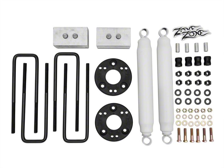
Shop Parts in this Guide
1. Park the vehicle on a clean, flat surface and block the rear wheels for safety.
2. Raise the front of the vehicle and support with jack stands at the frame rails.
3. Remove the front wheels.
4. 2011 and newer models equipped with EPAS (Electronic Power Assist Steering), disconnect the power steering control module connector to avoid arching of the contacts in the internal power relay from a hammer blow or impact wrench.
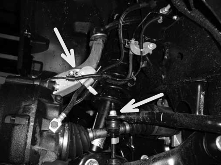
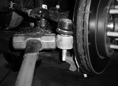
5. Disconnect the driver's and passenger's side front sway bar links from the sway bar. Save sway bar link nuts. Figure 1 Complete this portion of the installation on one side at a time
6. Disconnect the front brake line and ABS line from the steering knuckle. Save bolts. Figure 1
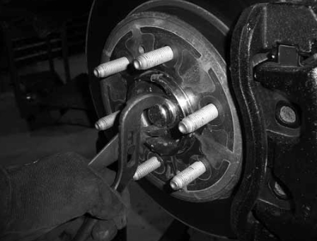
7. Locate the small dust cap on the hub. Figure 2 Carefully remove the cap using a pair of channel lock (or any wide jaw style) pliers. Save dust cap.
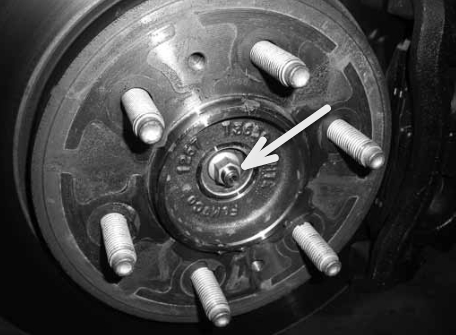
8. Remove the CV retaining nut (which was covered by the dust cap). Save nut. Figure 3
9. Remove the steering tie rod end nut from the tie rod end at the steering knuckle. Thread the nut back on a couple of turns by hand. Strike the knuckle near the tie rod end to dislodge it from the knuckle. Figure 4 Remove the nut and remove the tie rod end from the knuckle. Save nut.
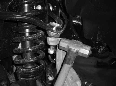
10. Remove the upper ball joint nut and thread back on a couple of turns by hand. Strike the knuckle near the ball joint to dislodge it from the knuckle. Figure 5 Remove the nut and remove the ball joint from the knuckle. Save nut. Allow the knuckle to rest back away from the front strut.
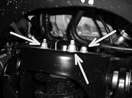
11. Support the lower control arm with an appropriate jack. Remove the three upper strut mounting nuts at the frame. Figure 6 DO NOT remove the center strut rod nut. Save nuts.
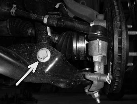
12. Remove the lower strut mount bolt/nut at the lower control arm. Figure 7 Lower the control arm and remove the strut from the vehicle. Save lower strut hardware.
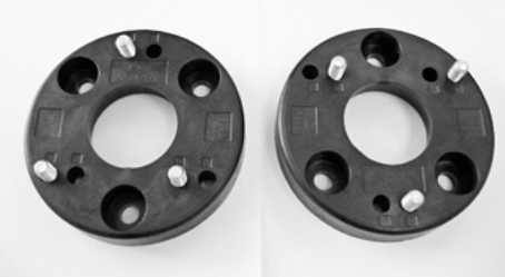
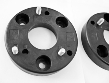
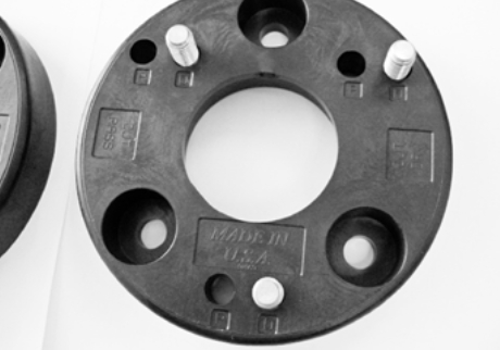
13. 2009-2013 Model Years: Locate the new strut spacers. Install the 7/16" bolts into the holes for correct side (P = Passenger, D = Driver). Figure 8A,B,C
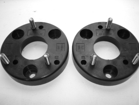
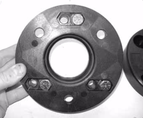
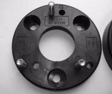
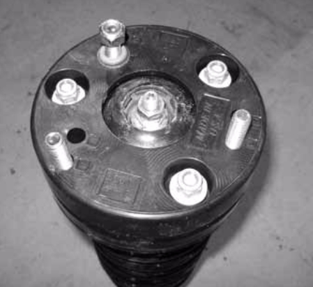
14. 2009-2013 Model Years: Install the new spacer on the strut and fasten with the original mount nuts. The spacers are labeled to indicate which side will face 'out' on the vehicle once they are installed . The studs need to be opposite of the factory studs. Figure 9 Torque nuts to 35 ft-lbs.
15. 2014 Model Year: Install the 7/16” x 2” bolts into the holes marked ‘D’ only, do NOT use ‘P’ holes for BOTH strut spacers. Figure 10a, 10b, 10c. All of the markings on the driver’s side are correct. The passenger’s side will use the ‘D’ holes and have the side labeled ‘OUT DRV’ face the outside of the vehicle. Figure 10a, 10b, 10c
16. Install the modified strut assembly into the upper frame mount by aligning the studs in the new spacer with the original mounting holes. Loosely fasten the strut with the provided 7/16" nuts and washers.
17. Install the bottom of the strut back into the original mount with the factory hardware, leave hardware loose. With the lower hardware installed, go back and torque the new upper hardware to 40 ft-lbs. F1213 Installation - pg. 9
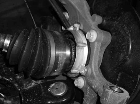
18. With the strut installed, reconnect the knuckle to the upper ball joint with the original nut. While connecting the upper ball joint, be sure that the CV shaft properly aligns into the hub. Figure 11 Torque ball joint nut to 85 ft-lbs.
19. Be sure the CV is properly seated in the hub and reinstall the original retaining nut. Torque nut to 20 ft-lbs. Reinstall the hub dust cap by tapping in place with a small hammer.
20. Reconnect the brake line and ABS line to the steering knuckle with the original bolt. Torque bolt to 10 ft-lbs. 21. Attach the steering tie rod end to the steering knuckle with the original nut. Torque to 100 ft-lbs.
22. With both sides complete, reconnect the sway bar links to the sway bar with the original hardware. Torque to 30 ft-lbs.
23. If equipped, re-connect EPAS control module connector.
24. Install the wheels and lower the vehicle to the ground. Torque lug nuts to 150 ft-lbs in a crossing pattern.
25. Bounce the front of the vehicle to settle the suspension. Torque the lower strut mounting bolts to 350 ft-lbs.
26. Check all hardware for proper torque. Check hardware after 500 miles.
27. The vehicle will need a complete front end alignment. Rear Installation Instructions NOTE: Complete the following instructions one side at a time. Do not attempt to drop the entire axle at one time.
1. Raise rear of vehicle and support with jack stands under frame. Remove wheels.
2. With axle firmly supported by jack stands remove the OEM shock. Place a hydraulic jack under the rear differential.
3. Loosen the OEM u-bolts that retain the spring to the axle. 4. With the hydraulic jack supporting the axle, slowly allow the axle to drop away from the leaf spring. Replace the jack stands for additional support.
5. Place the new block between the stock block and the leaf pack. Make sure the bump stop portion of the stock block is pointed the same direction as it was originally.
6. Slowly raise the axle with the hydraulic jack in order to assemble the blocks and leaf springs. Make sure that all of the locating pins are inside their female counterparts.
7. Install u-bolts with the supplied fasteners. Be sure the u-bolts are perpendicular to the axle before tightening.
8. Tighten the u-bolts to 100-120 ft-lbs. Replace wheels. Install correct Zone shocks recommended for this amount of lift. Replace the wheel.
9. Complete the above instructions for the other side of the vehicle.
