 FREE 1 to 3-Day Delivery on Orders $149+ Details
How to Install an AeroForce Air/Fuel Ratio Sensor Kit on Your 1996-2010 Mustang
Installation
Parts included:
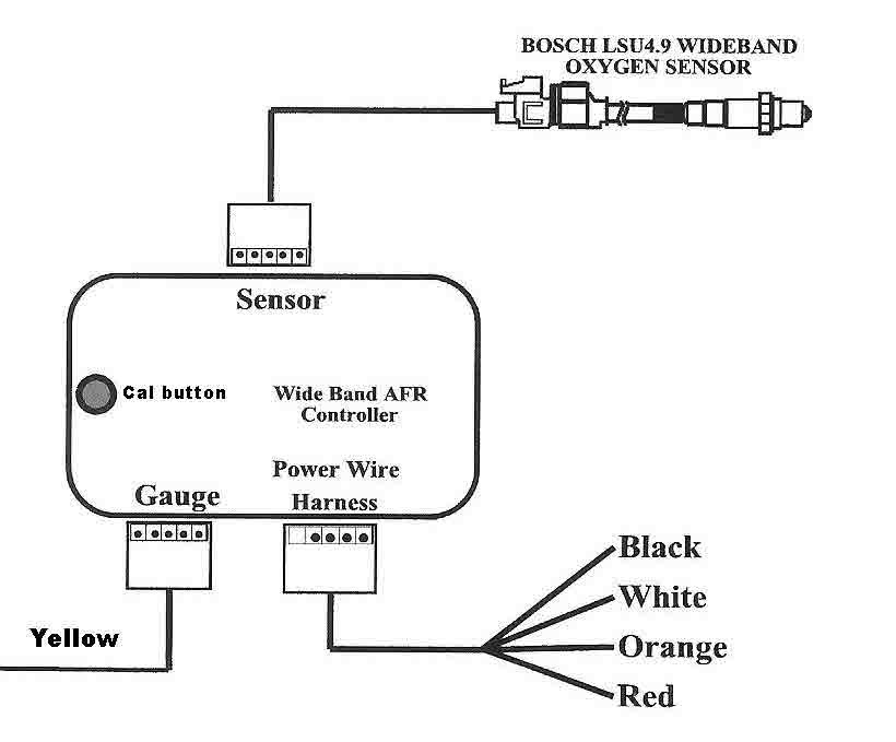
- Bosch LSU4.9 Oxygen Sensor
- Wideband AFR Controller
- Sensor wiring harness
- Power wiring harness
- Weld in bung
- Output wire
Installation
1. Install the provided LSU4.9 sensor by welding the exhaust bung into the exhaust pipe. You must use the provided M18x1.5 bung if your vehicle does not have an open or existing one. Make sure the location of the bung is no less than a minimum of 18 inches after the exhaust ports.
a. If you have a turbo charger, the bung must be installed no less than a minimum of 36 inches after the exhaust ports, but before the catalytic converter. This also applies if you are using unleaded race fuel.
b. The bung must be positioned in such a way that the sensor is at a minimum of 10 degrees from a horizontal position with the electrical connection up to prevent a collection of liquid at the element during the warm up phase.
2. Route and secure the wire harness from the sensor into the vehicle, close to the controller’s location.
3. The controller must be placed inside the vehicle away from the heat, water, moisture, dirt, and all moving parts. The controller also should be in an easy access location, so that it may be accessed for calibration, when necessary.
4. Once the controller is in its permanent location, secure and route the power wire harness for the controller.
a. Connect the red wire to a switched (ignition on) positive 12 volt source.
b. Connect the white wire to a switched (ignition on) positive 12 volt source.
c. Connect the black wire to a ground source (the wire going to pin 5 of theOBD2 port is a good source for signal ground but not required. It may eliminate the rare instance of a small error due to differences in ground potentials).
d. Orange wire is not used.
5. Install the output harness to the controller, and connect yellow output wire to the Interceptor gauge or data acquisition device/readout. If using an Interceptor gauge, please refer to the gauge instructions for further details.
6. Prior to use, the controller/sensor must be calibrated. Press and hold the button on the controller for 3 seconds to calibrate. The output will go to 5v (will read 19.8A/F on the Interceptor if conversion coefficients have been entered during this process). See calibration schedule for details.
Calibration Schedule
To obtain the most accurate results from the sensor, please follow the calibration procedure after installation. Calibration should be done with key on engine off when the vehicle has not been run for an hour or more or in free air:
1. For everyday driven vehicles:
a. Calibrate after installation
b. Calibrate again after 3 months of use
c. Calibrate twice a year or every 10,000 miles (whichever comes first)
2. For Race Vehicles only:
a. Calibrate after installation
b. Calibrate once per race weekend
3. Dynamometer Use:
a. Calibrate after installation
b. Calibrate every 2-3 days
If you replace or change your sensor you must follow the schedule as if it were a new installation.
Functions:
1. Prior to operation, the sensor must warm up for 30 seconds. This is a mandatory process every time the gauge and sensor are powered from a cold vehicle start. The output will remain at 5v (19.98-20.00 A/F) until the warm up phase is complete.
2. If the output of the controller becomes stuck at 20 then there is a sensor error detected. Check and confirm the connection of the sensor and wire harness to and from the controller unit. If the connections are secure and in place, press the button on the controller for 8 seconds to reset the controller to the original factory settings. Perform another calibration. If there is still no output contact [email protected]
Interceptor gauge configuration
To configure the Interceptor to read A/F ratio, you’ll need to enter the menu and choose the appropriate analog input. You’ll then be able to enter a conversion. The number to enter for slope is 2, and 10 for intercept. The value displayed on the gauge when this analog input is chosen will now represent A/F ratio. You will typically see 14.5-14.8 at idle and cruise, and under WOT the reading will go richer (lower) depending on your tune. Our testing has shown the sensor’s accuracy to be /- 0.1 decimal place.
If you prefer to see Lambda rather than A/F ratio, set the slope to 0.136, and the intercept to 0.68. A properly tuned vehicle will display a lambda of ~1 at idle or part throttle when in closed loop operation.
Lambda vs Air/Fuel ratio:
Gasoline AFR = Lambda x 14.65
Methanol AFR = Lambda x 6.47
Propane AFR = Lambda x 15.7
Ethanol AFR = Lambda x 9.00
CNG AFR = Lambda x 14.5
Warranty
Aeroforce Technology Inc. warrants to the consumer that this wideband kit will be free from defects in material and workmanship for a period of six (6) months from date of the original purchase. Products that fail within this 6-month warranty period will be repaired or replaced at Aeroforce’s option when determined by Aeroforce that the product failed due to defects in material or workmanship. This warranty is limited to the repair or replacement of the Aeroforce part. In no event shall this warranty exceed the original purchase price of the Aeroforce part nor shall Aeroforce be responsible for special, incidental or consequential dam ages or cost incurred due to the failure of this product. Aeroforce does not warranty the Bosch LSU4.9 sensor. Warranty claims to Aeroforce must be transportation prepaid and accompanied with dated proof of purchase. This warranty applies only to the original purchaser of product and is non-transferable. All implied warranties shall be limited in duration to the said 6 month warranty period. Improper use or installation, accident, abuse, unauthorized repairs or alterations voids this warranty. Aeroforce disclaims any liability for consequential damages due to breach of any written or implied warranty on all products manufactured by Aeroforce. Warranty returns will only be accepted by Aeroforce when approval is given and/or accompanied by a valid Return Goods Authorization (RGA ) number received from [email protected]. Product must be received by Aeroforce within 30 days of the date the RGA is issued.

