FREE 1 to 3-Day Delivery on Orders $149+ Details
How to Install an Auto Meter Pro-Comp Ultra-Lite Air/Fuel Ratio Gauge - Electric on Your 1979-2012 M

Shop Parts in this Guide
Installation
- Disconnect the negative (-) battery cable.
- Gauge can be mounted in a 21⁄16" dia. hole with brackets supplied. Gauge can also be mounted in Auto Meter Mounting Cup, or in Auto Meter Gauges Works Pods.
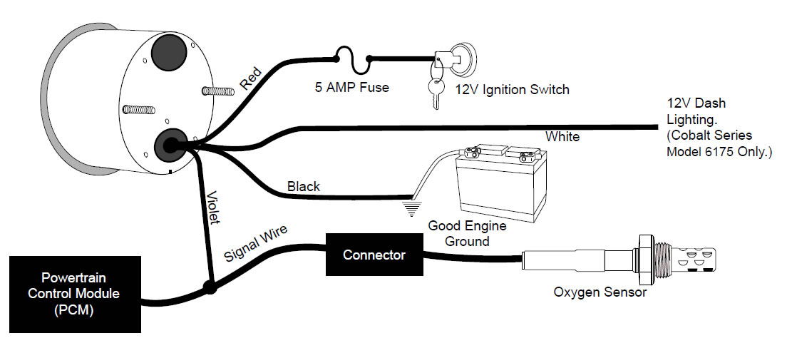
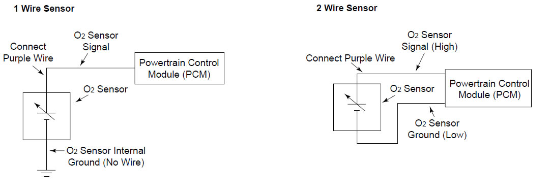
- Wire gauge as shown.
Red Wire: Connect to a fused and switched 12V positive source that is turned on and off with the ignition switch
Black Wire: Connect to good engine ground.
Violet Wire: Connect to oxygen sensor signal wire. Connect to vehicle wiring harness, not oxygen sensor since some oxygen sensors use shielded wire.
White Wire: Connect to 12V Dash Lighting. (Cobalt Series Model 6175 Only.)
NOTE: Only Cobalt Series has in dash lighting (Model 6175).
Mounting Sensor
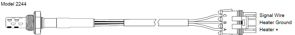
If your vehicle is not originally equipped with an oxygen sensor, purchase Auto Meter model number 2244. The heated oxygen sensor comes with a weld in boss, boss plug, and wiring harness with a weather pack connector. The oxygen sensor should be installed in a spot where exhaust from all cylinders flows past it.The oxygen sensor should also be installed as close to the cylinder head as reasonably possible so that the sensor reaches operating temperature quickly. If headers are used, the oxygen sensor should be installed in the collector. If cast iron manifold(s) are used, install the sensor in the pipe just below the manifold. Mounting in the left or right side is acceptable. If monitoring of both sides is desired, a second oxygen sensor can be used and a switch (purchased locally) can be wired to toggle back and forth between both sensors.
The Air / Fuel Ratio Monitor can be used with the following fuels.
| Fuels | Stoichiometric Air / Fuel Ratio |
|---|---|
| Unleaded Gasoline | 14.7:1 |
| Methanol | 6.5:1 |
| Ethanol | 9.0:1 |
| Propane | 15.7:1 |
OK for use with Nitrous Oxide.
The Stoichiometric Air / Fuel Ratio is the chemically correct ratio where theoretically all of the oxygen and all of the fuel are consumed. The mixture is neither rich or lean.
Oxygen Sensors
All oxygen sensors must be heated to at least 600° F before an accurate signal is produced.
Heated Oxygen Sensors
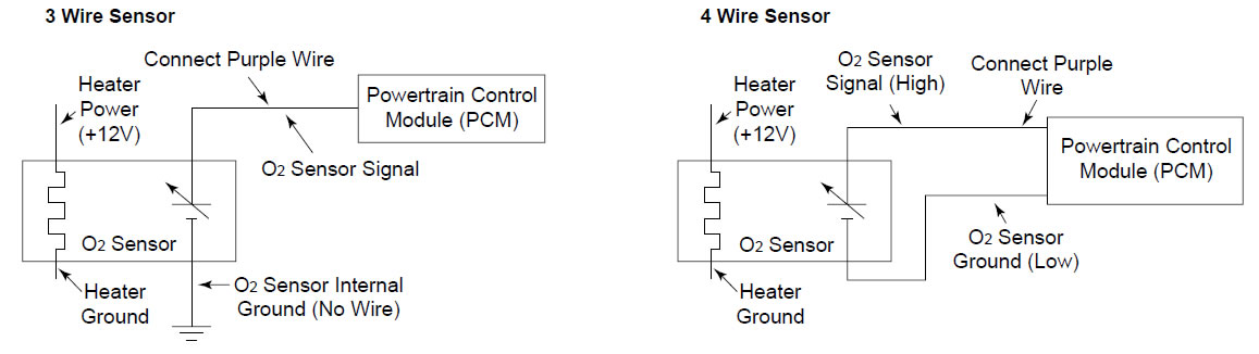
These sensors have an electrical resistance heater built in to them andwill come to operating temperature usually within 1 minute. These sensors have 3 or 4 wires, check with vehicle manufacturer, or wiring diagram for your specific vehicle to learn which wire is the signal.
WARNING
Do not connect ohm meter to oxygen sensor, or touch wire to ground or power. Damage to oxygen sensor will result. If a volt meter is to be used, only use a high impedance (10 mega ohm or higher) digital multimeter. NOTE:Do not disconnect wire to the computer.
Non-Heated Oxygen Sensors
These sensors rely on the hot exhaust gases to bring them to operating temperature. This may take several minutes and may even cool off when engine is idling. These sensors have 1 or 2 wires. On 2 wire sensors, one wire is ground and the other is the signal. Check with vehicle manufacturer or wiring diagram for your specific vehicle to learn which wire is the signal.
Warning
Fouling and/or permanent damage to the oxygen sensor over time will result if used with any of the following:
- Leaded gasoline and fuel additives containing lead
- 2 cycle gasoline (gas/oil mix)
- Diesel Fuel
- Nitromethane
- Excessively rich mixtures
When the engine is at heavy load the monitor should indicate rich. At cruising load the monitor will appear to be bouncing back and forth between rich and lean. This is normal. The computer is constantly adjusting the air / fuel ratio for performance and low exhaust emissions. See back page for more detailed information.
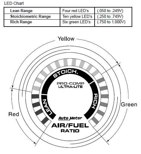
The Air/Fuel Ratio Monitor has 20 LED's. Four red that indicate lean, Ten yellow that indicate stoichiometric ratio, and six that indicate rich. One LED lights up for every 50mV of oxygen sensor output.
Air / Fuel Ratio Meter and Oxygen Sensor Operation
The A/F Ratio Meter is a voltmeter with a range of 0 to 1 Volt. The meter displays the output voltage of the vehicles oxygen sensor through 20 LED's. The first LED will come on at a voltage of .050V, the second at .100V, the third at .150V, etc (see LED Chart on previous page).
The stoichiometric (STOICH) air/fuel ratio is the chemically correct ratio. This means theoretically all of the oxygen and all of the fuel are consumed. The mixture is neither rich nor lean. However, due to the fact that combustion is never perfect in the real world, there will always be a small amount of oxygen left in the exhaust. This small amount that is left is what the oxygen sensor measures. The smaller the amount of oxygen that is left in the exhaust, the richer the A/F ratio is, and the higher the oxygen sensor voltage is. The on-board computer or Powertrain Control Module (PCM) monitors the voltage from the oxygen sensor. If the PCM sees an oxygen sensor voltage greater than .450V, it immediately starts to reduce the amount of fuel that is metered into the engine by reducing the on time to the fuel injectors. When this happens, the A/F ratio starts to go in the lean direction, and the oxygen sensor voltage starts to go down. When the voltage drops below .450V, the PCM immediately starts to increase the fuel metered to the engine by increasing the on time to the fuel injectors to produce a richer A/F ratio. This occurs until the oxygen sensor voltage goes above .450V. This repeating cycle happens very fast (many times per second). The PCM is said to be in closed loop. It is constantly monitoring the oxygen sensor voltage and adjusting the on time of the fuel injectors to maintain a STOICH A/F ratio. This A/F ratio produces the lowest harmful exhaust emissions, and allows the catalytic converter to operate at peak efficiency, therefore reducing the exhaust emissions further.
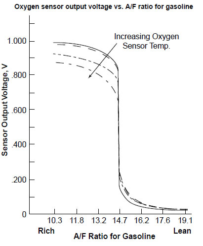
Since the oxygen sensor output is very accurate and sensitive at the STOICH A/F ratio, it will cause the A/F meter LED's to bounce back and forth rapidly. A very small change in A/F ratio causes a large change in oxygen sensor voltage as can be seen on the graph. This rapid cycling is normal when the PCM is in closed loop and trying to maintain a STOICH A/F ratio. The oxygen sensor is also very accurate at indicating an A/F ratio that is richer or leaner than STOICH. However it can not indicate the exact richness or leanness due to the fact that the oxygen sensor output changes with the oxygen sensor temperature and wear. As the sensor temperature increases, the voltage output will decrease for a given A/F ratio in the rich area, and increase in the lean area as shown on the graph.
During wide open throttle (throttle opening greater than 80% as indicated by the throttle position sensor) the A/F ratio will be forced rich by the PCM for maximum power. During this time the oxygen sensor will output a rich signal/voltage, but the PCM will ignore the signal. The signal will be ignored because it is not accurate for indicating the exact richness. The PCM is now in open loop, and relies on factory programmed maps to calculate what the on time of the fuel injectors should be to provide a rich A/F ratio for maximum power. The A/F ratio meter should indicate rich during this time.
During hard deceleration the PCM will command an extremely lean mixture for lowest exhaust emissions. This may cause the signal to go outside the range that the meter will indicate. When this happens, there will be no LED’s lit on the A/F meter.