FREE 1 to 3-Day Delivery on Orders $149+ Details
How to install a BBK High Flow Aluminum Fuel Rail Kit on your 1986-1993 Mustang
Installation Time
3 hours
Tools Required
- Hose Cutter
- T-20 Torx Ratchet
- Allen Wrench set
- Phillips head screwdriver
- 5/16" & 1/2" sockets
- Fuel Line Disconnect tool(spring lock type)
Shop Parts in this Guide
Installation
STEP 1 Disconnect negative battery terminal.
STEP 2 Remove intake hose between the mass air meter and throttle body.
STEP 3 Remove the distributor. (Use a marker pen to mark the position of the rotor on the lower cup of the distributor. Also note where the distributor base is at the engine block. Your distributor should have a hash mark on it for ease of reference. This will help reassembly)
STEP 4 If your intake manifold has a decorative plate (5.0 H.O.) on top, you will need to remove the plate. Use the T-20 Torx to remove the screws. Unclip the wiring harness locator from the manifold.
STEP 5 Disconnect the electrical, coolant, vacuum, and cable connections at the throttle body, EGR valve, fuel pressure regulator, IAC valve, and the upper intake manifold. (Some of the vacuum lines are underneath and behind the upper manifold)
STEP 6 Using a ½” socket and extension remove the upper intake manifold bolts.
Slide the manifold towards the front of the car and disconnect the vacuum lines that attach to the rear of the manifold and the PCV. Remove the upper manifold.
STEP 7 Unplug the wiring harness from the fuel injectors (Be sure to only pull on the plastic plugs, never pull by the wires.)
WARNING!
FUEL SYSTEM MAY BE UNDER PRESSURE. USE EXTREME CAUTION WHEN RELEASING PRESSURE. EXTINGUISH ALL OPEN FLAMES AND IGNITION SOURCES.
STEP 8 Remove the black plastic cap on the fuel feed line near the front end of the passenger side valve cover (near oil filler cap). While holding a rag over the valve to avoid fuel spray, carefully release any fuel system pressure by depressing the Schrader valve using a small screwdriver or pick.
STEP 9 Use the fuel line disconnect tools to separate the fuel feed and return lines from the injector rails.
STEP 10 Unbolt and remove the injector rails from the lower manifold (The fuel rails will have excess fuel in them, use caution when removing to avoid spillage)
STEP 11 Remove the fuel injectors from the lower manifold. (Check each injector to make sure that both of the O-rings are in place. The O-rings have a tendency to get stuck in the fuel rails)
STEP 12 Separate the fuel pressure regulator from the stock fuel rail. (Skip this step if you are installing an aftermarket regulator).
STEP 13 Inspect the injector tips and O-rings for cracks or damage. If you have any questionable items we recommend replacing them (available through auto parts stores).
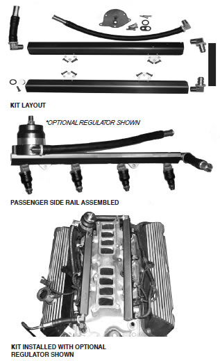
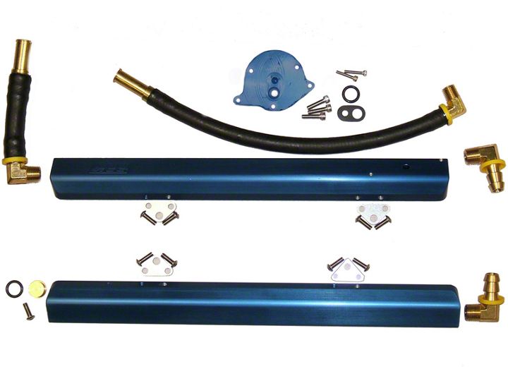
STEP 14 Install the supplied mounting tabs onto the fuel rails using 8 of the 9 supplied 10-32 x 5/8” button head screws.
STEP 15 Assemble the fuel pressure regulator mount and your choice of regulator using the 3 supplied screws and regulator- to- mount gasket.
STEP 16 Place one of the supplied O-rings into the groove in the bottom of the regulator mount and install the fuel pressure regulator/ mount assembly onto the rear of the passenger side rail. Fasten it to the rail using the supplied 6-32 x 3/4” screws.
STEP 17 Place the remaining O-ring over the fuel rail end cap and push the cap into the front end of the driver side rail. Secure it using the remaining 10-32 x 5/8” button head screw.
STEP 18 Thread the 1 of the supplied 90° fittings into the rear of each fuel rail until snug. Then continue tightening until the outlets will face each other once the rails are installed.
STEP 19 Push one end of the supplied crossover hose fully onto one of the 90° fittings.
STEP 20 Thread the long pre-assembled hose into the regulator mount until its snug. Then tighten it until it is following the rail forward to meet up with the stock fuel return line.
STEP 21 Thread the short pre-assembled hose into the front end of the passenger side rail until its snug. Then tighten it until it is pointing towards the passenger side of the car to meet up with the stock fuel feed line.
STEP 22 Insert the injectors into the rails (we recommend lightly lubricating the outsides of each O-ring to ensure proper seating).
STEP 23 (Follow for both rail/injectors assemblies) carefully guide each injector into its injector port on the lower manifold. Tighten the supplied fasteners through the fuel rail mounting tabs and into the lower manifold.
STEP 24 Determine the proper length for the crossover hose and cut it to fit. Push the cut end fully onto the other 90° fitting (if necessary, rotate the fittings to line up.)
STEP 25 Connect the spring lock fittings on the fuel rails and regulator to the stock fuel feed and return lines.
TESTING THE FUEL RAILS FOR LEAKS
TO AVOID SHOCK/ FIRE/WORSE, WE STRONGLY RECCOMEND FOLLOWING THE INSTRUCTIONS FOR THE NEXT PROCEDURE CLOSELY!
STEP 26 Disconnect the electrical connector from the ignition coil (this may require removing the plastic cover located between the battery and the strut tower).
STEP 27 If the car has automatic door locks or an alarm, be sure to leave the driver door open while following this step. Otherwise the doors might lock with the key in the ignition). With the negative battery cable disconnected turn the ignition key to the on position. While watching the fuel rails and connections, touch the negative battery cable to the negative terminal of the battery for 3 seconds then stop. (This will turn the fuel pump on momentarily and pressurize the fuel rails. If you have any leaks in the connections or fittings this will allow you to find and repair them before you put the upper intake manifold back on). Once you have verified that there are no fuel leaks in your system turn the key back to off.
STEP 28 Re-install the upper intake manifold and re-establish all electrical, coolant, vacuum, and cable connections at the throttle body, EGR valve, IAC valve, ignition coil, and the upper intake manifold.
STEP 29 If you followed STEP 3; re-install the lower cup, rotor, cap, and distributor wires.
STEP 30 Connect the intake hose between the mass air meter and throttle body.
STEP 31 Re-connect the negative battery terminal.