FREE 1 to 3-Day Delivery on Orders $119+ Details
Best Sellers


How to Install a Digital Shift Knob - Manual on Your 1979-2012 Mustang
Installation
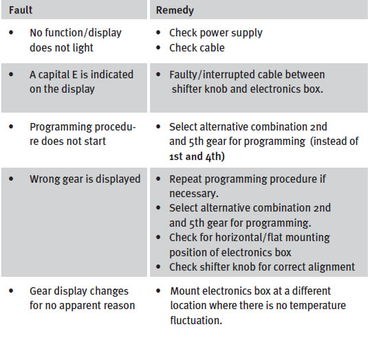
The digital gear display on the Indy- Cator shifter knob functions on the principle of calculating the difference between two electronic sensors that detect minimal changes in the shifter knob‘s position. The result is indicated on the display as the shifter knob changes gears. Therefore, it functions completely independent of the vehicle transmission. The display only changes when a change has been reliably detected as a gearshift.
This may require 1 to 1.5 sec. This gear display is intended to serve only as an aid. No warranty is given for the correctness of the gear number.
In the event that gears do not display correctly, the programming procedure should be repeated with the engine/transmission at operating temperature.
Depending on the particular type of vehicle and gear positions, brief cross fading in the display may occur at extreme acceleration. This is due to the physical characteristics of the sensors and is not a product or manufacturing defect.
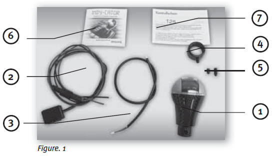
1. Indy-Cator shifter knob (1x)
2. Cable assembly and electronics box (1x)
3. Connecting data cable (1x)
4. Clamping ring (1x )
5. Set screws, length 10 mm & 14 mm (2x, one each)
6. Instructions for installation and use (1x)
7. Warranty Card (1x)
1.1.1
On some vehicles, the shifter knob is threaded on to the shift rod (e.g. VW, Vauxhall, Ford, etc.)
Check to see if the shift-lever boot is connected to the shifter knob. If it is not, simply turn or unscrew the shifter knob until it separates from the shift rod and then remove.
If shift-lever boot is connected to the shifter knob, carefully detach the shift-lever boot from the center console.
Turn the shifter knob and the shiftlever boot until it detaches from the shift rod, then remove both parts.
1.1.2
On other vehicles such as a BMW, the shifter knob is pushed on to the shift rod and can be pulled off.
1.2.1
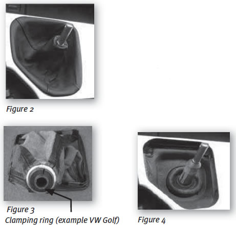
If the vehicle is one described under Item 1.1.1, the shift-lever boot is already removed with the shifter knob. Separate the shift-lever boot from the shifter knob; they are usually connected with a ring (Figure 3).
The ring must be removed carefully with a suitable tool. The shift-lever boot can then be separated from the shifter knob.
1.2.2
If the vehicle is one described under Item 1.1. (Figure 2), the shift-lever boot must be removed from the center console and pulled off over the shift rod until only the shift rod is visible (Figure 4).
2.1
Fit the shift-lever boot over the Indy-Cator shifter knob. This applies only to vehicles using this specifi c factory arrangement. The existing shift-lever boot may not be wide enough. In this case, it should be widened with suitable tools to enable it to be fi tted over the bottom end of the Indy-Cator shifter knob.
2.2
It is recommended to position the shift-lever boot between the shifter knob and clamping ring in order to keep the clamping ring covered with the clamping screw. On some vehicles, this is unfortunately not possible. In such cases, the clamping ring should be positioned over the shift-lever boot.
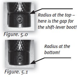
The position of the clamping ring must be follows:
- Where the shift-lever boot is in between, the clamping ring must be fi tted with the radius towards the top and the radius rests against the shift boot (Figure 5.0).
- Where there is no shift-lever boot in between, the clamping ring must be fi tted with the radius towards the bottom (Figure 5.1).
2.3
Install the complete shifter knob on to the shift rod and align it so that the front is facing the front of the vehicle (in the direction of travel). Push the shifter knob down on to the shift rod against the inner stop in order to prevent it from subsequently loosening. Use an Allen wrench to tighten one of the set screws to the shift rod. If the shift rod has a small diameter, use the longer set screw (14 mm); with a large shift rod diameter, the shorter set screw (10 mm) should be used.
2.4.1
Plug the connecting data cable into the side of the small electronics box and attach it – the adhesive strip is provided on one side of the box for this purpose – to a point that is protected from being bumped or moved in anyway (Figure 6).
2.4.2
The box must be secure and not subsequently slip!

Important note:
It is recommended that the electronics box is attached to a fl at surface (GASLOCK logo at the top); the direction of the cable is irrelevant. The electronics box should not be mounted near heating elements or air ducts to prevent heating or cooling.
It should not be in a location that is subject to cooling due to drafts or air conditioning vents. Take care not to mount the electronics box to any part of the vehicle subject to getting hot. Under certain circumstances, the heat can deform the box to the extent that the position of it can change.
According to our experience, this preferred mounting position ensures maximum accuracy and stability without incorrect gear displays!
Temperature differences between the shifter knob and electronics box can cause an intermittent incorrect display.
2.4.3
Connect the red wire to a power cable that is only energizer (“hot“) when the ignition is on (such as power to the cigarette lighter or similar device) and connect the black wire to a suitable ground. Be careful routing these wires to prevent any subsequent damage! Therefore installation by experienced persons or by a specialized vehicle repair shop is recommended!
2.4.4
After connecting the red wire to a power source and the black wire to ground, connect the electronics box to the shifter knob by plugging the other end of the connecting data cable into the small socket at the bottom of the shifter knob. Be very careful to plug the connector in correctly to prevent damage or malfunctions!
3.1
Starting the procedure
PLEASE READ THE FOLLOWING CAREFULLY!
After turning on the car‘s ignition and the Indy-Cator is on, the user is always asked whether the programming procedure should be started.
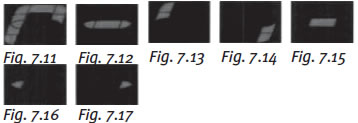
When the two segments at the top left of the display fl ash (see Fig.7.13), put the car into fi rst gear. If the car is already in fi rst gear, proceed to the next step. The segments at the bottom right of the display will then start to fl ash (see Fig. 7.14), which tell you to put the car into fourth gear. When you do this, the system remembers the gearshift positions of these gears. You are then asked again to reselect gears 1 and 4. If this is successful, the programming procedure can start. If gears 1 and 4 are not selected at this time, the programming procedure is stopped.
3.2
Perform the programming procedure:
Switch on ignition! All gear positions of the system are displayed by a number or segment fl ashing on the display in sequence. Then, the indicated gear must be selected by the user. Gear selection takes place in two phases as the vehicle is positioned on two different gradients. In the fi rst phase, the vehicle should be facing forward on a gradient and positioned in the opposite direction for the second phase.
The end of the fi rst phase is indicated by the display of a line (see Fig. 7.12). Between the two phases, you have about 60 seconds to change the position of the vehicle. The lapse of this time is indicated on the display by a downward count from 9 to 0.
The gear positions are taught in the phases in the following order: gears 1 to 6 (see Figs. 7.2 - 7.7), reverse gear (see Fig. 7.11), center neutral position (see Fig. 7.15), left neutral position (see Fig. 7.16 keep in position here) and right neutral position (see Fig. 7.17 keep in position here). If the vehicle does not have a sixth gear, obviously it cannot be selected. When requested in the fi rst phase to select the sixth gear, the gear shift lever should remain in the previous position and not moved. The system recognizes the shift lever has not moved and skips to the second phase.
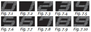
This also applies in the absence of a fi fth gear. Once the programming phase is completed, the system stores the gear positions and subsequently starts to recognize the gear position (fl ashing ceases).
However, a programming teach phase can be initiated each time the system is switched on by putting the gear shift lever in fi rst and fourth gears twice (see Section 3.1).
The programming procedure can be interrupted by switching off the power supply by turning off the ignition.
This can be helpful if errors are made during the procedure.
Each time the ignition is switched on, the d isplay fl ashes for several seconds. If the fi rst and fourth gears are not selected within the given time (as described), the electronic display changes to a normal mode the last programming assignment is displayed.