FREE 1 to 3-Day Delivery on Orders $149+ Details
Wiring your foglights to work with your driving lights (94-00)
Installation
Installation
This Mod will require the parking lights OR the headlights to be on, for the fog lights to operate (Advantage: you don't have to run around with your headlights on.) {Disadvantage: The fog light switch, and the ash tray light don't illuminate when you go to high beam (depending on the year model), and when you get to your destination and start to get out, the vehicle will start dinging to remind you that you left the parking lights on. The wiring color codes should be the same ('95 & '98 colors matched).
1. Disarm the SRS (airbag) system by disconnecting the negative battery lead, and then the positive lead. Wait two (2) minutes before continuing.
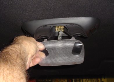
** If you decide not to disconnect the battery, disable the overhead interior lights, by pulling the bulb out of one of its clips. Don't touch the bulb glass with your fingers - it can cause it to burn out prematurely (either pry it out of the clip or use a paper towel). You can now work with the door open, and not drain your battery! The lens can be popped out with a small screwdriver. Mine had 2 slots on each side of the lens - carefully pry it up, and then remove the lens. Notice that there are four plastic tabs on the lens, that lock onto the light assembly. Be careful not to break them off, by prying too hard or too fast. It only goes back on one way!
2. Remove the lid on the center console glove box, either before or after the box, depending of the year model. There are about three screws on the hinge area. All are Philips head screws.
3. Remove the rubber pads near the front edge of the box (they press in and out), and then remove the screws that are in the recess (Figure 1). On some models there may be extra screws holding the box in. (Note: I uninstalled a 96 and installed a 99 console in my 1996 Cobra. I found that there are only three screws holding in both model years. All are phillips head screws).
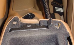
Figure 1
4. Pull up on the box, and remove it (For the 1994-1997 you may have to pull it up by the cupholder. Be careful, even though the cupholder is useless in that console, you don’t want to break it).
5. Locate an 8 wire harness connector (Figure 2), near the parking brake. Follow the harness to the left side of the console, and you'll see where it may be held in place with a plastic plug (with several little lips on it) see red arrows. The plug may be have been inserted from the top OR the bottom. Pull or pry (careful of the wire harness) the plug out of the hole. It may be stubborn, but WILL come out. Mine was pushed in from the bottom, so I used an icepick to push down and get it loosened a bit, and then a small screwdriver, underneath, to pry it out. If for some reason, there is an excess of play in the harness, you may be able to work on it without disconnecting it. The plug is reuseable, unless you really mangle it with pliers. It keeps the harness from wandering around and getting hung up in the brake mechanism, and/or rattling.
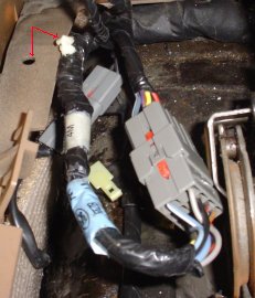
Figure 2
6. Disconnect the harness connector. This is simple, but do to the crowded spaces, some owners have given up at this point. Carefully push out on the clips on the sides of the connector (Figure 3) just a little bit (I used small and/or long screwdrivers - fingernails will break off), and at the same time - pull it apart (Figure 4). Note: the two clips are all that keep the connector from coming apart. They are flexible, but if you pry them out too far they will either break off, or become deformed and won't spring back enough to lock the connector halves together. Hold the connector in the palm of your hand and push the screwdriver blade underneath one clip and then turn the blade slightly (Figure 3) and the clip will raise up. If you're applying pulling pressure on the connector at the same time, one of the clips should hang up long enough for you to do the same thing on the other clip. If one of the clips break off, you're still okay. The remaining clip will hold the connector together. If both of them break, you can always use a small plastic tie-wrap to hold the harness together. The alternative would be to replace the connector, and if you're in this situation in the first place, you certainly don't want to try and replace the connector!
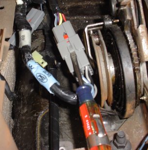
Figure 3
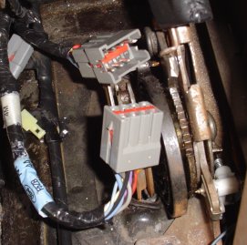
Figure 4
7. Look at the connector half that's nearest the rear of the vehicle (this is the only half you'll work with)... On the side of the connector, push "in" and "up" on the small red tab (Figure 5) the "red" divider in the center of the connector will rise. Remove the "red" divider. Make a note of the alignment slots on the side of the divider, for re-installation.
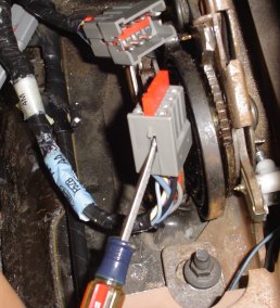
Figure 5
8. See Figure 6, below - Locate the red/black and the blue/red wires on the back of the connector (2nd from R/H side). You want to reverse the positions of these two wires. In the center of the face of the connector, there is a gray tab next to each wire position - See Figure 7, below. Each wire is soldered/crimped to a female pin that's locked into place by one of the gray tabs.
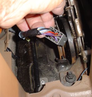
Figure 6
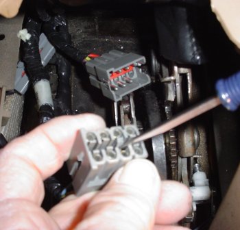
Figure 7
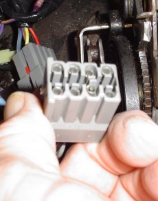
Figure 8
8 (Continued). Start with either wire - if there is electrical tape or insulation wrapped around the wires within 1 or 2 inches of the connector, remove part of it, to allow for movement of the wires (Figure 6, above). This is a perfect time to cut your finger or one of the wires - be careful! With a small blade screwdriver, gently push the gray tab towards the center of the connector to unlock the pin (Figure 7, above), and at the same time, push down on the female pin next to the tab. With the blade held in the right position, it's fairly easy. If the pin doesn't move, the tab hasn't been moved far enough to unlock the pin. Once the pin starts to move, it's unlocked (Figure 8, above) - pull the wire out from the back of the connector (you may have to use small needle-nose pliers to push the pin out from the other side (Figure 9 & 9a) - remember, these pins have to mate up to the other half of the connector, so don't bend or crush them because they won't go back together)(Figure 9b). Remember which side of the connector it came from. Remove the other wire in the same manner. Carefully relocate each of these 2 wires in the harness (so there is no tension pulling on the wires) to line up with the opposite hole they came out of. Caution - don't bend the wire where it attaches to the pin - it may break off (if this happens, you're going to have to solder it back on to the pin, or buy a new pin & crimp the wire into it)! Push each wire into its new location, and make sure it locks in place. The top of the pin should be flush with the rest of the pins in the connector. The gray tabs should be back in their locked position.
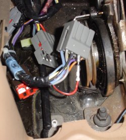
Figure 9
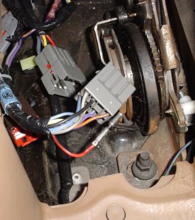
Figure 9a
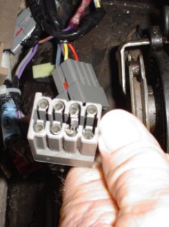
Figure 9b
NOTE: Figure 9b shows what happens when the pin bends or distorts! I disconnected it to take a new photo, and when I reinserted the pin into the connector, it came out the other side of the connector about 1/4 inch, and fractured the gray locking tab. The locking tab is now ineffective, but the red divider will keep the wire from migrating. I was able to force the pin back into and out of the connector, straighten it out, and then finish it up. If you break or fracture one of the gray locking tabs, it'll be difficult to get the divider back in, BUT it will go.
9. Reconnect both halves of the connector (inspect the tabs on the side, to make sure they are in the locked position), anchor the harness back to its original position with the plastic plug.
10. Connect Pos & Neg battery leads, and perform a test of the fog lights, with the light switch in different positions. Note whether or not the fogs go off when you hit high beam, and the overall effect on the ashtry light.
11. Reinstall glovebox insert OR the lid, depending on the year model (the '94-97 lid is held down with a magnet - you have to align the magnet portion that's mounted on the console itself, with the slot in the top of the box insert) (Figure 10). If the magnet doesn't align with the slot in the box insert, it could break the magnet assembly, so push the box in slowly, and align the magnet with the slot. I broke mine, the first time I slammed the box back into place. The '98-00 has a mechanical latch, instead of a magnet.
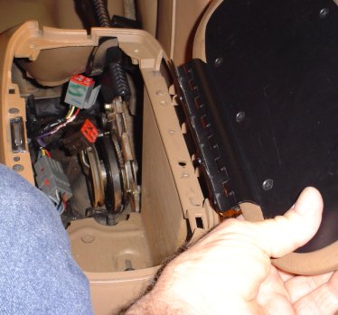
Figure 10
12. Re-install the lid and mount screws (unless this has already been done), and rubber pads. You're done! Go cruise!