 FREE 1 to 3-Day Delivery on Orders $149+ Details
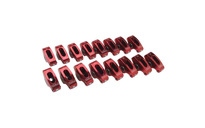
How to Install Edelbrock Red Performance Roller Rocker Arms - 1.6 Ratio on Your 1979-1995 5.0L Musta
Shop Parts in this Guide
Installation
IMPORTANT NOTE: Proper installation is the responsibility of the installer. Improper installation will void your warranty and may result in poor performance and engine or vehicle damage.
DESCRIPTION: The Edelbrock Roller Rocker Arms have been designed for use on Small Block Ford as well as Small and Big Block Chevy engines.
Part numbers ending in zero are complete sets of 16 rockers, while part numbers ending in a one are individual replacement rockers.
INSTALLATION: Rotate the main trunnion of the rocker arm so that the flat machined surface is facing up, then lower the rocker arm onto the rocker stud so that the roller tip is contacting the valve and the pushrod is seated into the cup. Rotate the engine by hand until cylinder #1 is at TDC on the compression stroke (the rotor on the distributor should be lined up with cylinder #1’s spark tower). If you are using hydraulic lifters, rotate the pushrod between your fingers as you tighten the rocker arm adjustment nut, once you start to feel drag in the pushrod you are at zero lash. Continue tightening the adjustment to set the lifter preload according to your camshaft installation instructions, then use an allen wrench to tighten the posi-lock. If you are using mechanical lifters, use a feeler gauge while tightening the adjustment nut to set your valve lash to the clearance listed in the camshaft installation instructions, then use an allen tool to tighten down the posi-lock. Complete this procedure for both the intake and exhaust rockers, then rotate the crankshaft 90° and repeat this procedure on the next cylinder in the firing order. Continue doing so until all 16 rocker arms have been properly installed and adjusted. Proper operation can be verified by rotating the crank by hand and observing the motion of the pushrod and the position of the roller on the valve tip. The pushrods must never contact the cylinder head walls and the roller tip must maintain at least 50% contact with the valve tip during a full rotation of the camshaft. If the pushrod contacts the cylinder head or the roller fails to maintain sufficient contact with the valve tip you will need to loosen your rocker stud and adjust your pushrod guideplate until proper valvetrain alignment is achieved.
PLEASE study these instructions carefully before beginning this installation. Most installations can be accomplished with common tools and procedures. However, you should be familiar with and comfortable working on your vehicle. If you do not feel comfortable performing this installation, it is recommended to have the installation completed by a qualified mechanic. If you have any questions, please call our Technical Hotline at: 1-800-416-8628, 7:00 am - 5:00 pm, Pacific Standard Time, Monday through Friday.
IMPORTANT NOTE: Proper installation is the responsibility of the installer. Improper installation will void your warranty and may result in poor performance and engine or vehicle damage.
DESCRIPTION: The Edelbrock Roller Rocker Arms have been designed for use on Small Block Ford as well as Small and Big Block Chevy engines.
Part numbers ending in zero are complete sets of 16 rockers, while part numbers ending in a one are individual replacement rockers.
INSTALLATION: Rotate the main trunnion of the rocker arm so that the flat machined surface is facing up, then lower the rocker arm onto the rocker stud so that the roller tip is contacting the valve and the pushrod is seated into the cup. Rotate the engine by hand until cylinder #1 is at TDC on the compression stroke (the rotor on the distributor should be lined up with cylinder #1’s spark tower). If you are using hydraulic lifters, rotate the pushrod between your fingers as you tighten the rocker arm adjustment nut, once you start to feel drag in the pushrod you are at zero lash. Continue tightening the adjustment to set the lifter preload according to your camshaft installation instructions, then use an allen wrench to tighten the posi-lock. If you are using mechanical lifters, use a feeler gauge while tightening the adjustment nut to set your valve lash to the clearance listed in the camshaft installation instructions, then use an allen tool to tighten down the posi-lock. Complete this procedure for both the intake and exhaust rockers, then rotate the crankshaft 90° and repeat this procedure on the next cylinder in the firing order. Continue doing so until all 16 rocker arms have been properly installed and adjusted. Proper operation can be verified by rotating the crank by hand and observing the motion of the pushrod and the position of the roller on the valve tip. The pushrods must never contact the cylinder head walls and the roller tip must maintain at least 50% contact with the valve tip during a full rotation of the camshaft. If the pushrod contacts the cylinder head or the roller fails to maintain sufficient contact with the valve tip you will need to loosen your rocker stud and adjust your pushrod guideplate until proper valvetrain alignment is achieved.
Related Guides
-
Installation
-
Installation
-
Installation

