FREE 1 to 3-Day Delivery on Orders $119+ Details
Best Sellers


How to install a Ford Racing 4.6L 3V Crate Engine Control Pack on your 2005-2009 Mustang
Installation Time
3 hours
Tools Required
- Wire Strippers
- Digital Volt/Ohm Meter
- Solder Gun / Solder
- Electrical Tape / Shrink Tubing
- Hand Drill
- Hole Saw
- Utility Knife
Installation
1.0 INTRODUCTION
This kit was developed by Ford Racing to allow performance enthusiasts to easily install today’s modern muscle into street rods from yesterday. We have developed this system to take the complexity and mystery out of installing a Mustang Electronic Throttle Control (ETC) engine into your vehicle.
This kit minimizes the effort required by the installer and includes a new Ford Racing Power Distribution Box (FRPDB) which includes all fuses and relays required to operate the production engine, including the air conditioner, intercooler pump (5.4L Only), and cooling fan.
Important Note: The FR power distribution box (FRPDB) and FR wiring harness in this kit must interface to a production engine harness for model years 2007-2009. The FRPDB and wiring harness will not interface correctly to the production engine harness for 2005-2006 4.6L 3V, 2010 4.6L 3V or 2010 5.4L 4V. If you own one of these harnesses, you must purchase an engine harness for a 2007-2009 Mustang. The correct engine harness is available for purchase from Ford Racing.
2.0 OVERVIEW
This booklet provides a step by step guide for the preparation and installation of the controls pack. Please read the instructions thoroughly before starting the installation. If you have any questions, please contact Ford Racing Technical Support at (800) 367-3788.
3.0 COMPONENTS INCLUDED
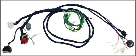
3.1 Cowl Wiring Harness
CM-14A005-A
This harness is labeled and includes all connections required to power up and run your ETC engine.
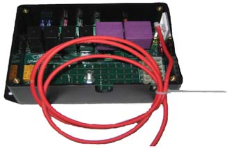
3.2 Ford Racing Power Distribution Box
CM-14A068-A
The FRPDB plugs directly into two wiring harnesses: 1) the CM-14A005-A included in this kit and 2) the wiring harness on your engine (See previous note regarding compatibility with 05-06/10 model year engine harnesses). This PDB contains all relays and fuses needed for engine, air conditioner, intercooler pump (5.4L Only), and cooling fan control.
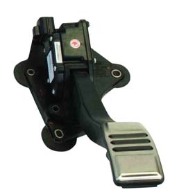
3.3 Accelerator Pedal
7R3Z-9F836-A
This pedal is required for correct electrical interface with the PCM. (Car will not run without it) Using this pedal eliminates throttle cable routing problems.
3.4 Powertrain Control Module (PCM)
CM-12A650-463V (4.6L 3V)
CM-12A650-54SC (5.4L Supercharged)
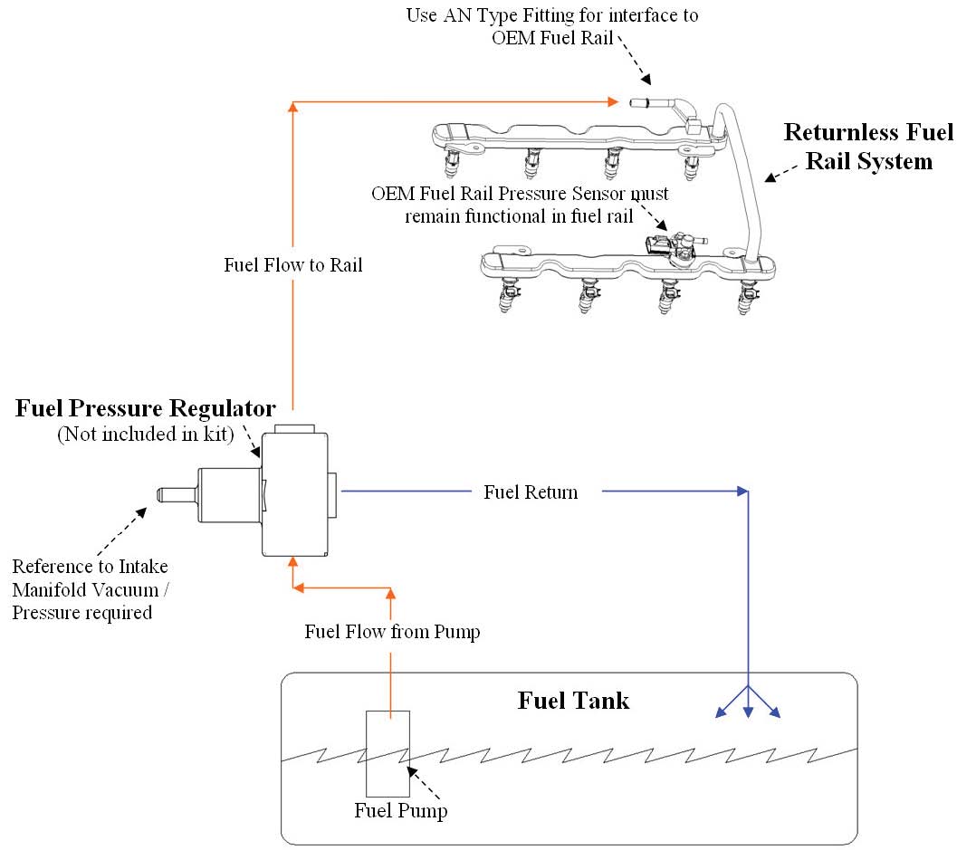
Commonly referred to as the engine computer, or ‘brain’, this PCM is calibrated for operation with a non-modified Ford Racing cold air kit and ‘Return Style’ fuel system. This PCM will NOT work with a ‘Returnless’ fuel system as used on factory Mustang vehicles. Should only be used with Premium Fuel.
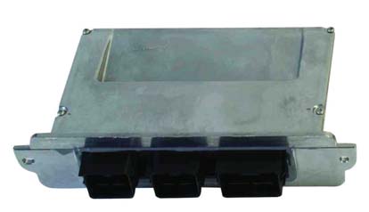
NOTE: Due to the fuel system requirement described above, installation of this PCM in ANY Production Mustang vehicle will result in a no-start condition!
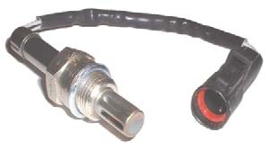
3.5 HEGO Sensor
5C5Z-9F472-AA
The Mustang production Heated Exhaust Gas Oxygen sensor provides feedback to the PCM for closed loop air fuel ratio control.
5.0 PRE-INSTALLATION OF HARNESS AND PARTSs
5.1 Disconnect the battery prior to performing any wiring modifications.
5.2 Identify where the cowl harness can pass through on the Right (Passenger) side of the bulkhead. You will need to determine the proper location to cut a hole for the harness to pass through. Check for any wires, hoses, etc. that may become damaged by the hole saw.
5.3 Use a center punch to mark the location of the center of the hole. By using the center punch, this will keep the drill bit from ‘walking’ while you are cutting through the bulkhead.
5.4 Drill hole to size required to allow OBD II and accelerator pedal connectors to pass through from engine to passenger compartment. Clean any sharp edges with a file or die grinder.
5.5 The grommet will need to be cut in order to be installed onto the harness. Using a utility knife, carefully make one cut starting from the inside of the grommet and cutting outwards. It is always safest to pull the knife away from you while cutting.
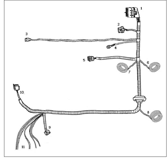
5.6 Route the harness through the hole, starting from the engine compartment side; pass the accelerator pedal connector (Page 8, Connector #10), OBD II connector (Page 8, Connector #9), and blunt leads into the passenger compartment.
5.7 Route the accelerator pedal connector, OBD II connector, and blunt leads under the dashboard and towards the driver (left) side of the vehicle.
5.8 Route the remaining Fuel Pump Lead (Green wire) along the passenger side floor boards to the fuel pump at the rear of the vehicle.
5.9 Install the PCM and PDB. This harness design assumes PCM (computer) and PDB (power distribution box) installation in the front of the engine compartment on the passenger (right) side; however some customers have successfully located the PCM and PDB components in the passenger compartment glove box area. Either location is acceptable as long as all connectors are able to mate without excessive strain on the harness wiring.
7.0 HARNESS INSTALLATION
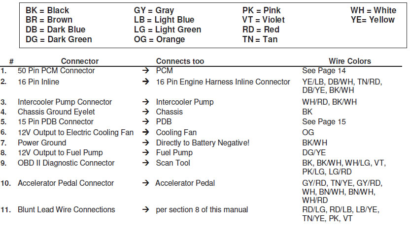
7.1 Attach main engine harness connector (large green and white connector) to the PDB. Use a Phillips screwdriver to gently snug the mounting screw for this connector. Access to this screw is through a hole in the back side of PDB.
7.2 Attach the PCM Connector (Page 8, Connector #1) to the cowl pocket (middle connector) of the PCM
7.3 Attach the Auxiliary Inline Connector (Page 8, Connector #2) to the mating Inline Connector on the engine harness.
NOTE: IF USING THIS KIT FOR A 2005 / 2006 MUSTANG 4.6L 3V ENGINE OR 2010 4.6L or 5.4L ENGINE, YOU MUST REMOVE AND REPLACE THE EXISTING ENGINE WIRING HARNESS WITH A 2007-09 MODEL YEAR ENGINE WIRING HARNESS!!!
7.4 Attach the 15 pin PDB Connector (Page 8, Connector #5) to the PDB. Leave the lid off of the PDB for now, to allow for trouble-shooting if necessary.
7.5 Using a sheet metal screw, attach the eyelet (Page 8, Connector #4) to the inner fender or bulkhead. Verify that you have a good reliable ground path from the battery negative post to the location being used for this eyelet on the chassis. In general, the resistance from the battery ground to this chassis location should be less than 0.1 ohm.
7.6 (5.4L Only) Route the supercharger Intercooler Pump Connector (Page 8, Connector #3) down towards the bottom of the radiator, and find a suitable location to mount the intercooler pump which will still reach this connector. After mounting the intercooler pump, attach the connector.
7.7 Find a mounting location for the Accelerator Pedal. You should ensure that the mounting location is sufficiently strong so it will not fatigue over time from the constant usage of the accelerator pedal. If necessary, fabricate an addition support plate for mounting the accelerator pedal. Once the pedal is mounted, attach the Accelerator Pedal Connector (Page 8, Connector #10)
7.8 Attach the OBD II Diagnostic Connector (Page 8, Connector #9) under the dashboard on the driver (left) side of the vehicle. You should be sure that the connector, once mounted, does not interfere with any part of your body while in the seated position.
Important Note on the Starting System
This kit includes connections and installation instructions for PCM controlled engine starting; however, it is not required that the customer utilize this option. Customers may choose to use their existing non-PCM controlled starting system if desired. If non-PCM controlled starting is used, step 8.2 C may be omitted, and unused blunt leads should be cut to ~2” length and sealed using heat shrink.
8.0 WIRING CONNECTIONS
8.1 Locate each of the Blunt Leads. This is where you will need to make all of the soldered connections for the harness.
8.2 You may use the diagram on page 7 as a reference for the following connections:
- Blunt Lead 1 – Ignition Switch Position (Red/Light Green Wire): Connect this wire to a SINGLE SOURCE on the ignition switch that provides 12 Volts when the key is in either the ‘Start’ (cranking) or ‘Run’ position. It is imperative that this circuit be reliable, the PCM will interpret an intermittent voltage on this signal as a request to shut down the engine! (Hint, if your engine shuts down after a hard launch check here first).
- Blunt Lead 2 – Fuel Pump (Dark Green/Yellow): Connect to Fuel Pump positive. Separate ground for fuel pump must be provided. The fuel pump will be running any time key is on.
- Blunt Lead 3 – Starter Motor Request (Red/Light Blue): Connect to start node of ignition switch so that 12 volts is provided when engine starting is requested.*
- Blunt Lead 4 – Clutch Position (Light Blue/Yellow): This circuit must be grounded either directly to ground or through an optional customer provided clutch pedal switch.* (PCM will not engage the starter without proper ground/switch)
- Blunt Lead 5 - CTO (Tan/Yellow): This wire is the tachometer lead. This is not a mandatory connection.*
- Blunt Lead 6 - VSOUT (Pink): Intended for use with aftermarket electronic speedometer. Contact Ford Racing for help with calibration.*
- Blunt Lead 7 – A/C Control (Violet): Connect this wire to the dash control A/C switch. Battery power to this wire will engage the A/C compressor clutch.*
- Blunt Lead 8 – Cooling Fan (Orange): Connect to 12V feed of Cooling Fan. Separate ground must be provided.*
- Blunt Lead 9 - Not applicable
- Blunt Lead 10 – Power Ground (Black): Ground Wiring must be connected directly to negative lead of battery.
* If feature not used cut lead so ~2” of wire remains; use heat shrink to seal exposed wire.
9.0 Fuel System
The PCM is calibrated for a return style fuel system, not the returnless fuel system provided on factory mustangs.
Notes:
- The required fuel system pressure is different depending on whether you are using a 4.6L or 5.4L engine.
- Set regulator to maintain the following constant delta fuel pressure across injector:
4.6L 40psi
5.4L 50psi
- Use only AN type fuel fitting to interface with OEM fuel rail.
- Do not remove original OEM fuel rail pressure sensor.
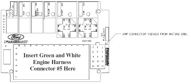
10.0 FRPDB Installation
10.1 Connect the main power lead from the FRPDB to the battery positive terminal
FRPDB Layout
11.0 INITIAL START UP
The following information is offered assuming you have adhered to each of the previous steps of this installation manual. This would include making certain that the main power leads are hooked up, the PCM & PDB are connected, and all of the required connections within the ‘9 Pin Disconnect’ have been made.
11.1 Check all fluid levels, electrical and fluid connections.
11.2 Pressurize the fuel system by turning the key on. Inspect the entire fuel system (from tank to engine) for leaks. If any leaks are found, do not proceed further until these have been corrected.
11.3 Start Engine. Check for leaks and/or noises that may indicate a problem.
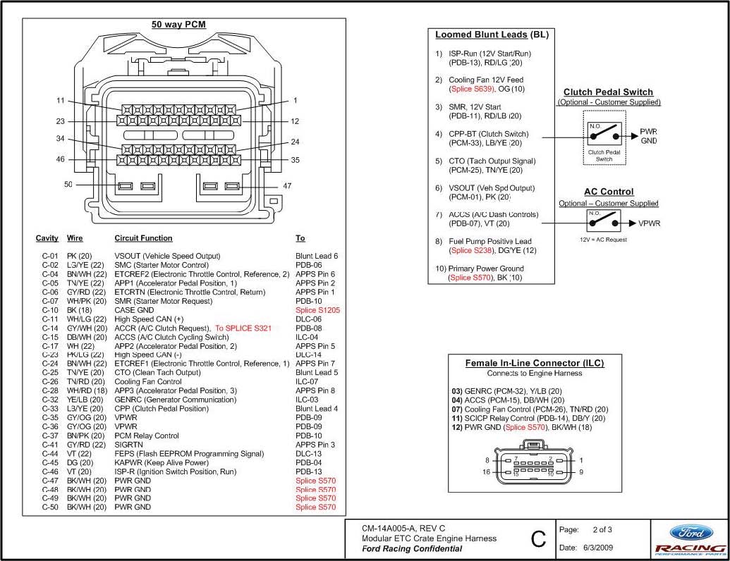
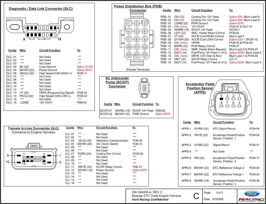
13.0 CONNECTOR FACES AND WIRE USAGE SCHEMATIC