 FREE 1 to 3-Day Delivery on Orders $119+ Details
Best Sellers


Push Start Ignition Button ('05-'10) - Installation Instructions
Installation Time
2 hours
Tools Required
- Phillips Head Screwdriver
- Flathead Screwdriver
- 1/4" Nut Driver
- Needle Nose Pliers
- Hand File
- Wire Strippers/Cutters
- Electrical Tape and/or Head-Shrink
- Solder Gun (Not Required, but Highly Recommended)
- Heat Gun (Not Required, but Highly Recommended)

Shop Parts in this Guide
Installation
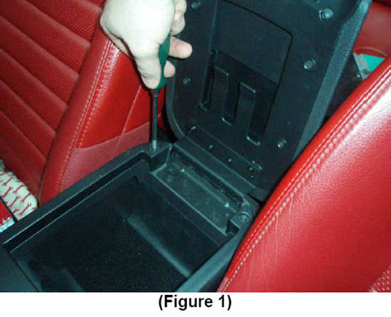
1. Start by removing the (2) screws found at the rear of the center console underneath the armrest. (Figure 1).
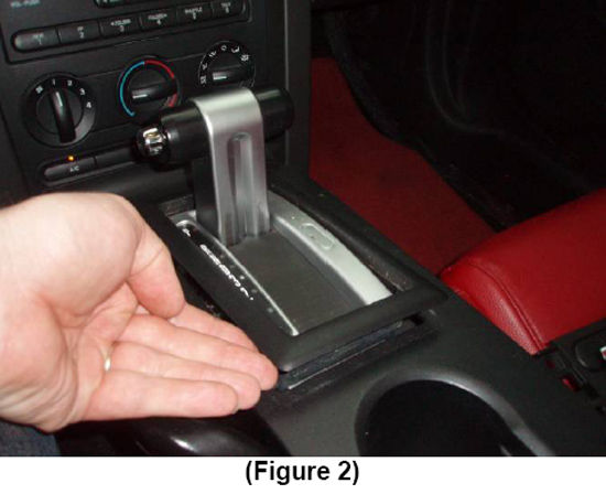
2. Remove the trim plate which surrounds the Shifter Handle (Auto) or Shifter Boot (Manual). (Figure 2)
Note:Manual transmission applications will require removing the shifter knob first. This can be removed by simply unscrewing it in a counter-clockwise direction.
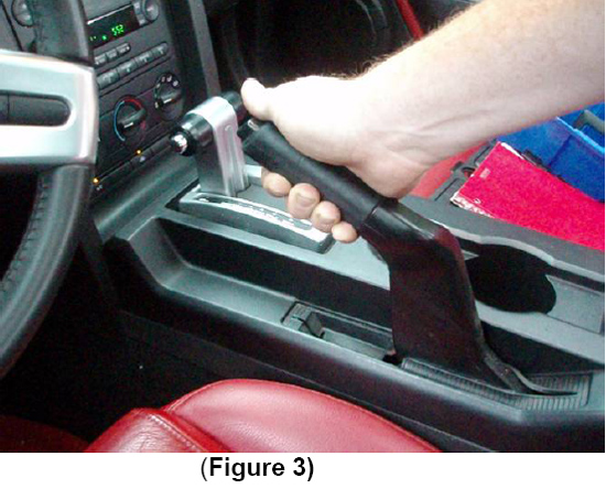
3. Fully extend the E-Brake handle. Again, this will need to be FULLY extended to allow adequate clearance for removal of center console cover. (Figure 3)
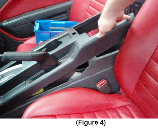
4. Lift the center console cover beginning from the rear, and slide it past the emergency brake handle. (Figure 4)
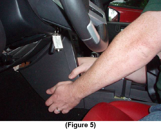
5. Remove the side cover from the center dash panel on the driver side. This is retained by clips, and can be removed by grasping from the bottom, then pulling straight back. (Figure 5)
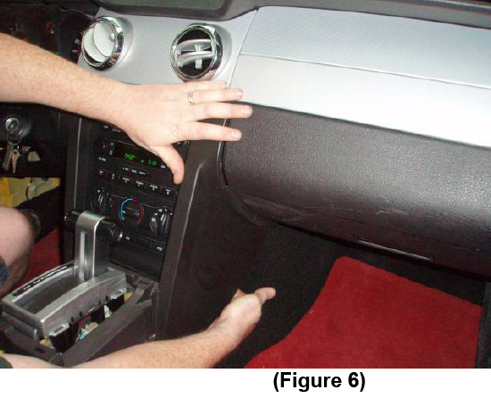
6. Repeat the same for the side cover of the center dash panel on the passenger side. (Figure 6)
7. Remove the (6) screws that retain the radio trim plate, using a ¼” nut driver.
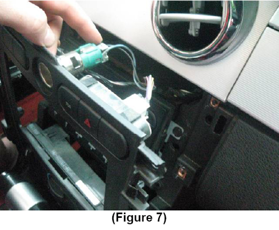
8. Carefully remove the (3) plugs from behind, at the top of the radio trim plate. (Figure 7)
Note:These can be easily removed by depressing the tab located on the connector as seen in Figure 7. Each of the (3) individual connectors has a ‘release’ tab similar to that shown in Figure 7.
9. Carefully remove the connector located at the bottom of the radio trim plate on the passenger side.
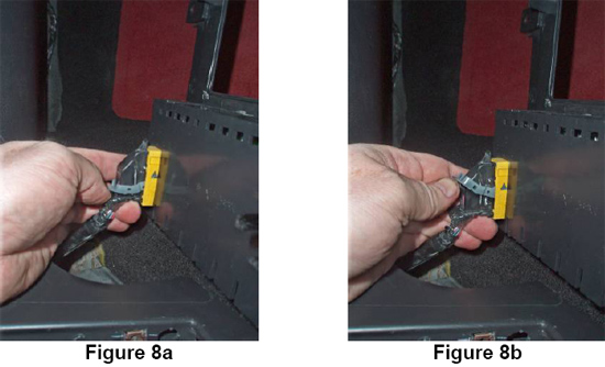
Note:The passenger side uses a unique connector on the ‘A/C – Heater’ selector switch. It can be removed by lifting the locking lever as shown in Figure 8a & Figure 8b.
Additional Note:This photo was taken from the driver side to more easily identify the connector lever.
10. Remove the remaining connector at the bottom of the radio trim plate located on the driver side.
Note:This connector attaches to the blower speed selector. Depress the release tab for removal.
11. Remove the radio trim plate.
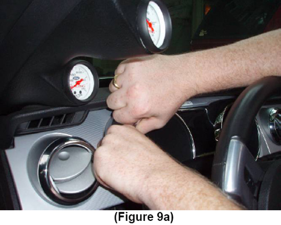
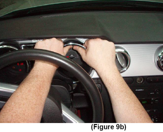
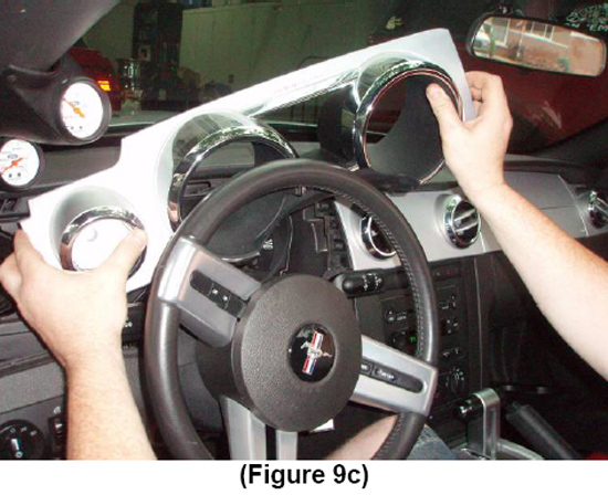
12. Remove the instrument cluster trim plate. This is retained by clips and can be removed by firmly grasping the cluster trim panel and pulling directly outwards as seen in Figure 9a, 9b, & 9c.
Note:You may need to release the steering wheel adjustment lever at the bottom of the steering wheel.
Additional Note:This particular step is not mandatory, but it will make it easier to route the wires of the “START ENGINE” push-button to the ignition switch connector.
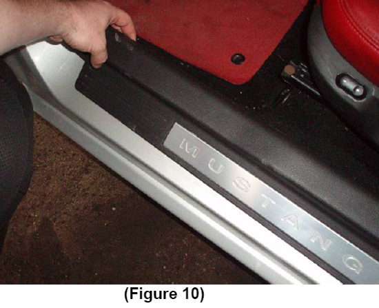
13. Remove the rocker panel cover on the driver side. This cover is retained by clips and can be simply pulled straight up. (Figure 10)
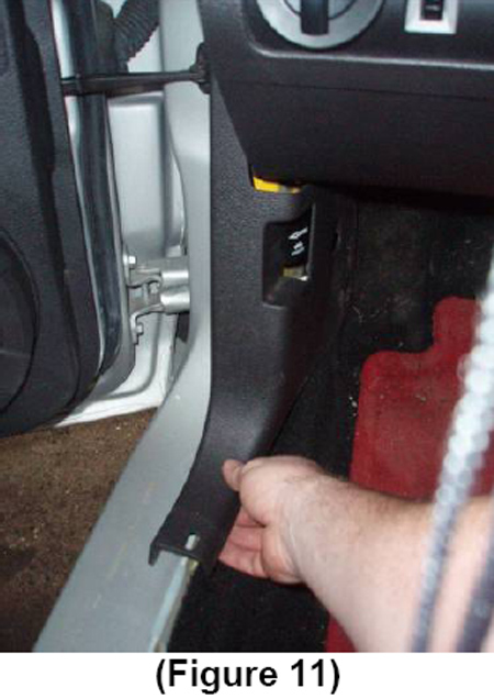
14. Remove the driver side kick panel by grasping from the bottom and pulling straight back. (Figure 11)
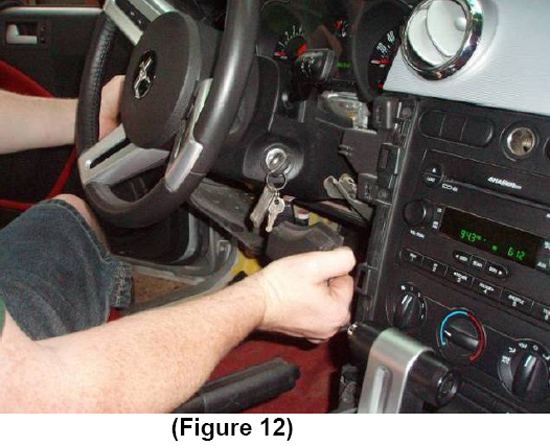
15. Remove the (2) screws located beneath the dash panel using the 1/4 ” nut driver.
16. CAREFULLY begin to remove lower dash panel cover. (Figure 12)
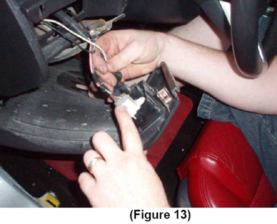
Note:You will need to remove the (2) connectors which attach to the headlight switch. (Figure 13)
Note:These can be easily removed by depressing the tab located on the connector as seen in Figure 13.
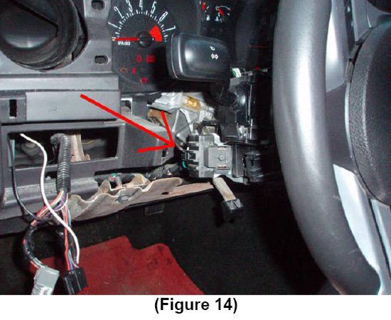
17. Remove the Lower Steering Column Cover by removing the 3 Phillips head screws. This will expose the ignition switch connector on the left hand side of the steering column. (Figure 14)
18. Prepare the Radio Trim Panel to accept the “START ENGINE” push-button.
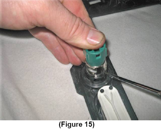
19. Begin by removing the 12V power supply receptacle. You will need to locate the locking tabs which retain the cylinder within the plastic ring. Using a small flathead screwdriver, pry the tabs away. Be aware that it will probably be necessary to damage the plastic retaining ring and it will not be re-usable. (Figure 15)
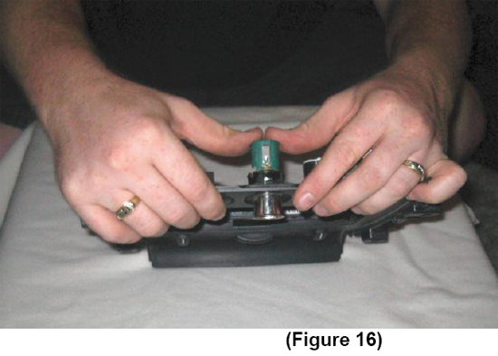
20. Once the locking tabs have been removed, press the cylinder from the radio trim panel and discard.
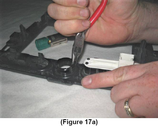
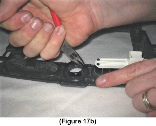
21. Remove the remaining plastic ring from the mounting hole. The use of needle nose pliers may make it easier to fold the tabs in for removal. Discard of the plastic ring. (Figure 17a & Figure 17b)
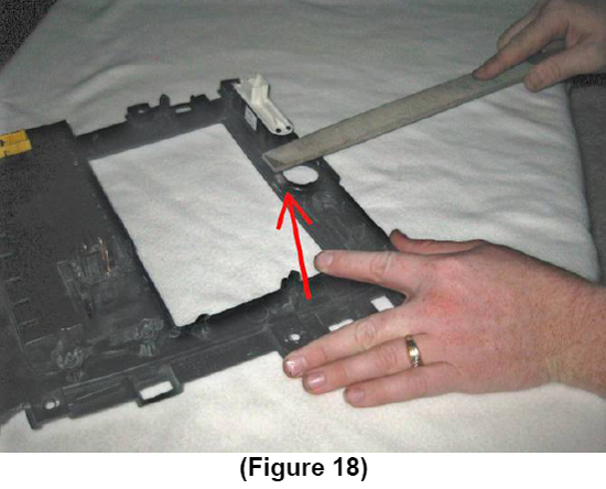
22. Using a hand file, you will need to remove some material from the backside of the mounting hole prior to installing the “ENGINE START” push-button. The material to be removed is located on the backside of the radio trim plate at the bottom of the mounting hole. This clearance is required so that the threaded portion of the push-button can expose enough threads to be properly tightened by the locking nut. (Figure 18)
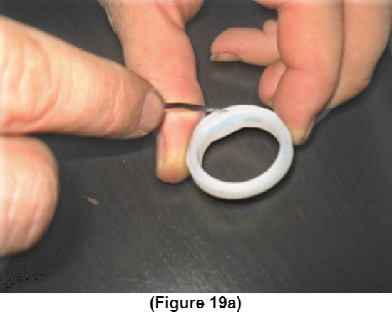
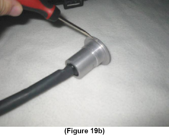
23. Install the supplied spacer onto the “ENGINE START” push-button, being certain to properly position the recessed step of the spacer towards the backside of the push-button. When properly installed, the step of the push-button will fit neatly into the recessed step of the spacer. (FIGURE 19a & Figure 19b)
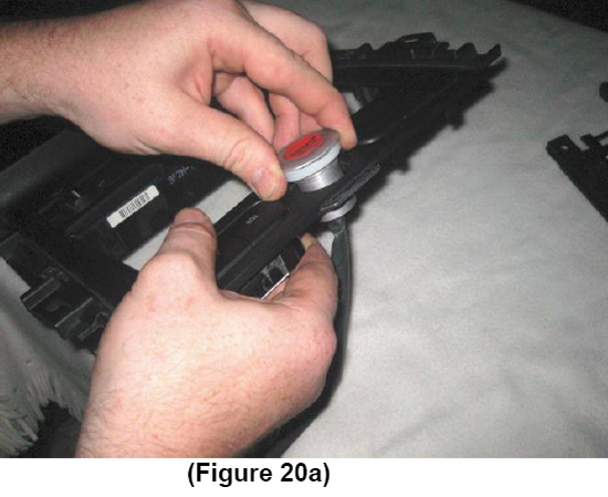
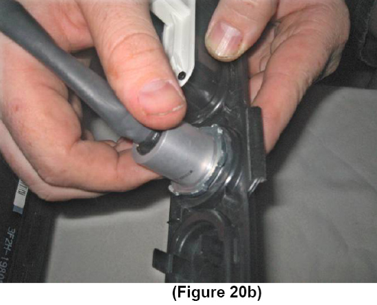
24. Place the “ENGINE START” push-button into the mounting hole of the radio trim plate, and tighten the lock nut.
Note:Depending on the amount of threads available, you may need to reverse the direction of the locking nut to insure that an adequate amount of threads are engaged. (Figure 20a & Figure 20b)
25. Attach the supplied pigtail connector to the “ENGINE START” push-button connector.
26. Reinstall the radio trim panel, while carefully routing the wiring harness towards the ignition switch connector previously referred to in Figure 14.
27. Disconnect the ignition switch connector, referred to in Figure 14. There is a release tab for easy removal.
28. On the ignition switch connector, there is a GREEN wire on the far outside. You will need to cut this wire loose from the ignition switch connector. Attach this GREEN wire to either wire of the “ENGINE START” push-button pigtail; it does not matter which one.
Note:For this connection, you may use the supplied Quick Disconnect Heat-Shrink Terminals, but for best results, it is recommended that you solder this connection and Heat-Shrink or tape the exposed splice.
Note:Failing to cut this GREEN wire from the connector, will still permit the vehicle to be started with the key.
Note:For 2010 models, use the blue wire with the white stripe
29. On the opposite end of the GREEN wire in the ignition switch connector, there is a WHITE wire on the far outside. You will need to SPLICE into this wire with the remaining wire coming from the “ENGINE START” push-button pigtail.DO NOT CUT THIS WHITE WIRE!!!
Note:You may use the supplied Crimp-Lock connector, but for best results, it is recommended to solder this connection and Heat-Shrink or tape the exposed splice.
Note:For 2010 models, use the light gray wire with the purple stripe
30. Once all of the above necessary connections have been made, re-attach the radio trim panel using the (6) screws that were removed upon disassembly.
31. Re-attach the battery cable.
32. Confirm that the vehicle is in Neutral or Park, and test the installation by starting the vehicle. You will need to turn the key to the ‘RUN’ position for the “ENGINE START” push-button to work.
33. Once you have determined the proper function of the “ENGINE START” push-button, re-assemble the dash panel and center console, using the instructions provided, in reverse order starting at STEP 17.
Installation instructions provided by Manufacturer.
