 FREE 1 to 3-Day Delivery on Orders $119+ Details
Best Sellers


Ford Racing Speedometer Recalibration Tool ('05-'10) - Installation Instructions
Installation
Installation on 2005-2010 Mustang:
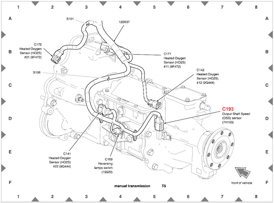
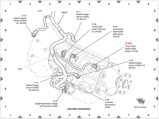
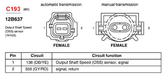
1. Identify and disconnect the Output Shaft Speed (OSS) connector from the transmission.
2. Identify the signal output wire. The wire colors are typically BLUE/YELLOW on the OSS ( ) signal side, and GRAY/RED on the OSS (-) return side. Remove the harness wrap to expose approximately 6 inches of the OSS wire leads, and cut the BLUE/YELLOWsignal wire, insuring that there is enough wire remaining on each side to splice in the wires coming from Speed-Dial.
Note:DO NOT CUT THE GRAY/RED WIRE!!!
3. For the 2010 Mustang, the OSS ( ) signal wire is GRAY/ORANGE, This is the wire that will get cut. The OSS (-) return wire is GREEN/WHITE.
DO NOT CUT THE GREEN/WHITE WIRE!!!
4. Once the BLUE/YELLOW OSS ( ) signal wire has been cut, attach the GREEN wire from Speed-Dial to the BLUE/YELLOW cut wire coming FROM the transmission. The GREEN wire on Speed-Dial is the SIGNAL IN.
5. Now attach the WHITE wire from Speed-Dial to the remaining BLUE/YELLOW cut wire which leads INTO the vehicle harness. The WHITE wire on Speed-Dial is the SIGNAL OUT.
6. Splice the RED wire (using solder and heat shrink) from Speed-Dial to a 12V KEY-ON voltage source. This RED wire should have voltage ONLY when the ignition key is in the 'RUN' position.
7. Finally, attach the BLACK wire from Speed-Dial to a ground source.
Note:For best results, this ground source should be checked for continuity to the negative side of the battery. An optimum ground path should measure less than 0.5 ohms to the negative battery post. (When measuring resistance, always make sure the key is in the OFF position.)
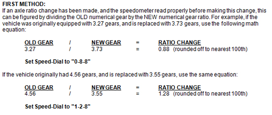
Speed Setting Procedure
Installation instructions provided by Ford Racing
