 FREE 1 to 3-Day Delivery on Orders $149+ Details
How to Install Fuel Rail Covers - Titanium Silver on Your 2005-2010 Mustang GT
Installation Time
1 hours
Tools Required
- 8mm Deep Well Socket
- 10mm Socket
- Ratcheting Nut Driver
- 1/8" Allen Wrench (supplied with kit)
- Flathead Screwdriver
-Fig 1 shows the stock engine bay before installation of the fuel rail covers. Note: this car has the factory plenum intake cover with Running Pony Logo that was part of Ford’s Appearance Upgrade Package. –Fig 2 shows the parts included in the kit. Carefully unpack and inventory the parts for this kit. Note that the fuel rail mounting brackets are stamped “DRIVER” and “PASSENGER” to identify which side they mount to.

Figure 1
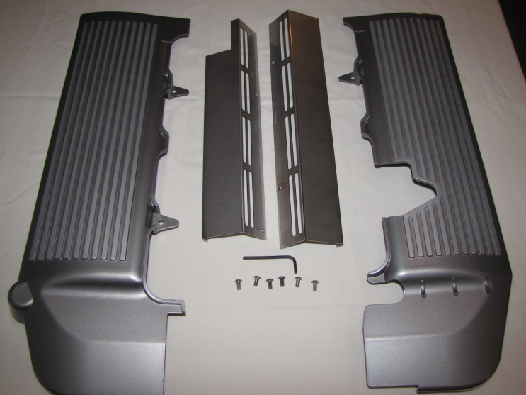
Figure 2
Cars that came with the factory plenum cover must have the cover removed temporarily when installing the fuel rail covers. Use the 8mm socket to remove the two nuts from the studs at the front of the throttle body –Fig 3. Pry the rear of the plenum cover up from the two studs on each side of the intake near the rear of the cover. The mounting brackets on the plenum cover have rubber insulators that mount over the intake and throttle body studs. Pull the cover forward and up off its mounting points –Fig 4 and safely stow it away until the fuel rail covers have been installed, then reattach it in the reverse order of its removal. The covers easily scratch, so be careful handling them. Note that the plenum cover is available from American Muscle as a separate item or as part of a kit with the fuel rail covers and/or fuse box cover. At a minimum, the plenum cover is preferred with the fuel rail covers for aesthetic reasons.
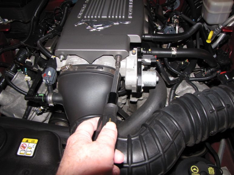
Figure 3
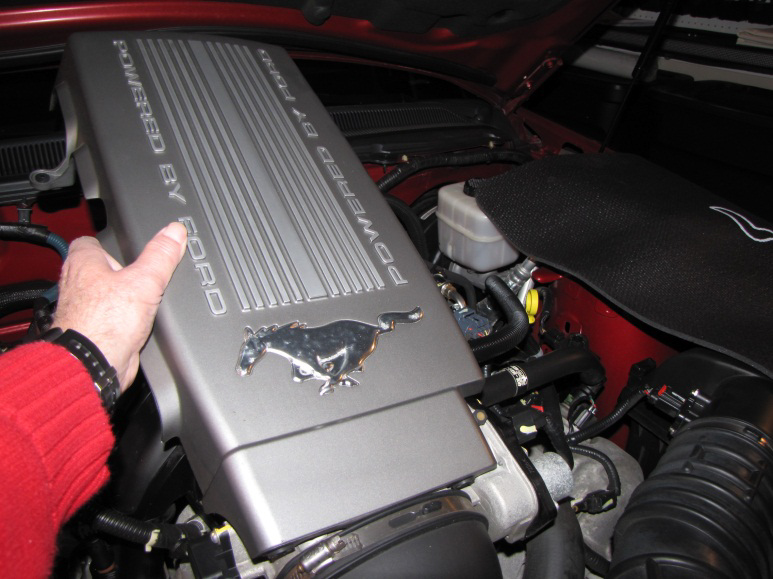
Figure 4
Remove the engine oil dipstick and set it aside until the fuel rail installation is complete –Fig 5. Next, remove the vacuum tube by pushing on the small end of the green clips and pulling the hose connectors off their mounts –Fig 6. Set the vacuum tube aside to be reinstalled later.
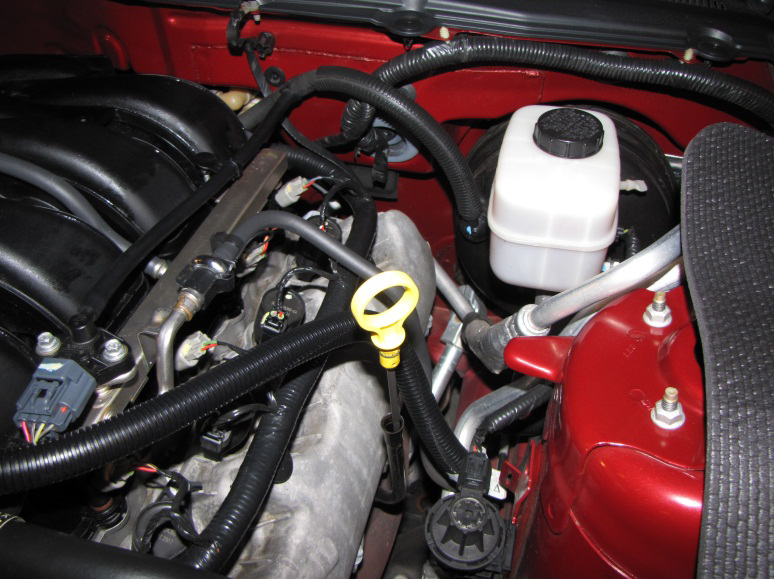
Figure 5
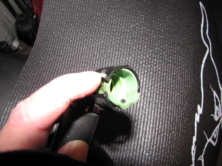
Figure 6
Pry the wire harness jam clips off the studs located on the cam covers in four placesindicated in –Fig 7. The clips are partially hidden by the large wiring harnesses. The jam clips fit very tightly on the threads of the studs and it may be necessary to use a flat blade screw driver to loosen them and then twist while pulling them up off the studs. Pulling on the large wiring harness also helps free the clips –Fig 8.
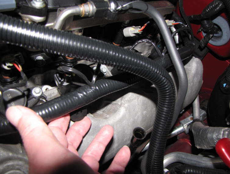
Figure 7
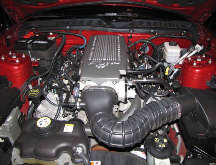
Figure 8
Identify the drivers side and passenger brackets. Push the passenger side bracket onto the bare studs on the passenger side cam cover –Fig 9. Make sure the bracket is bottomed out on the cam cover. Note that It may be necessary to coerce the bracket –Fig 10 because the tolerances for centering them on the studs is very tight.
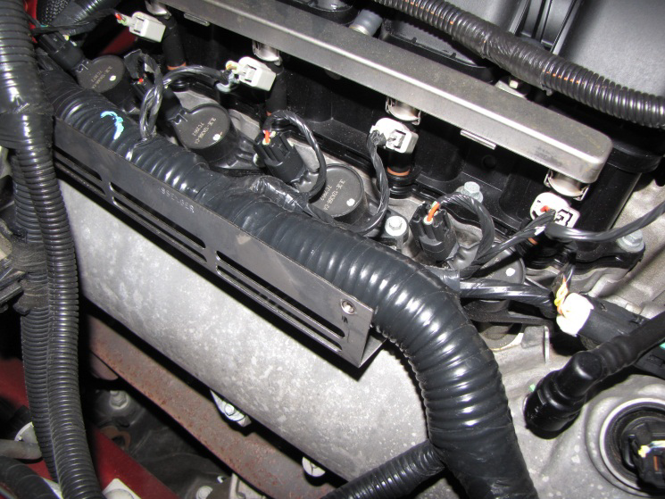
Figure 9
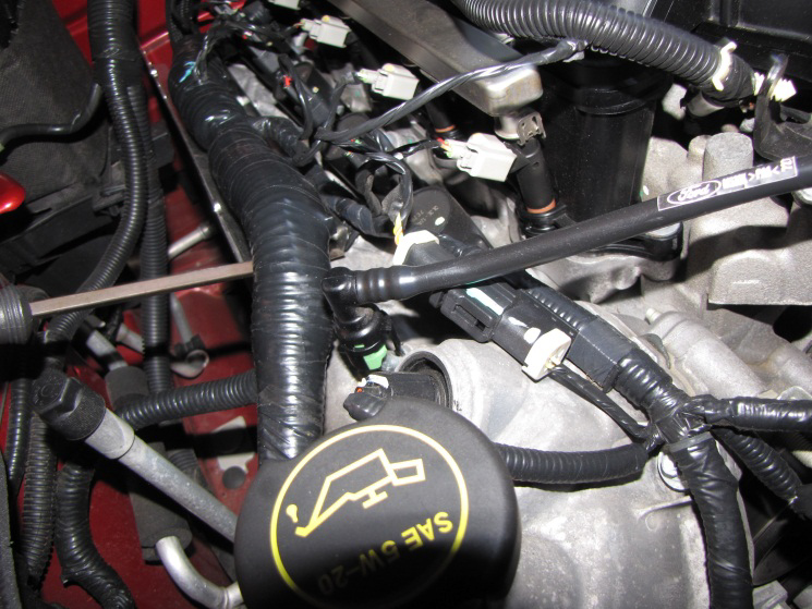
Figure 10
Fix the passenger side bracket in place by pushing the jam clips back onto the cam cover studs making sure the large wiring harness is positioned inside the bracket –Fig 11. Repeat the bracket install procedures for the driver’s side ensuring that the bracket is bottomed out on the valve cover and that the large wiring harness is on the inside of the bracket before replacing the jam clips –Fig 12.
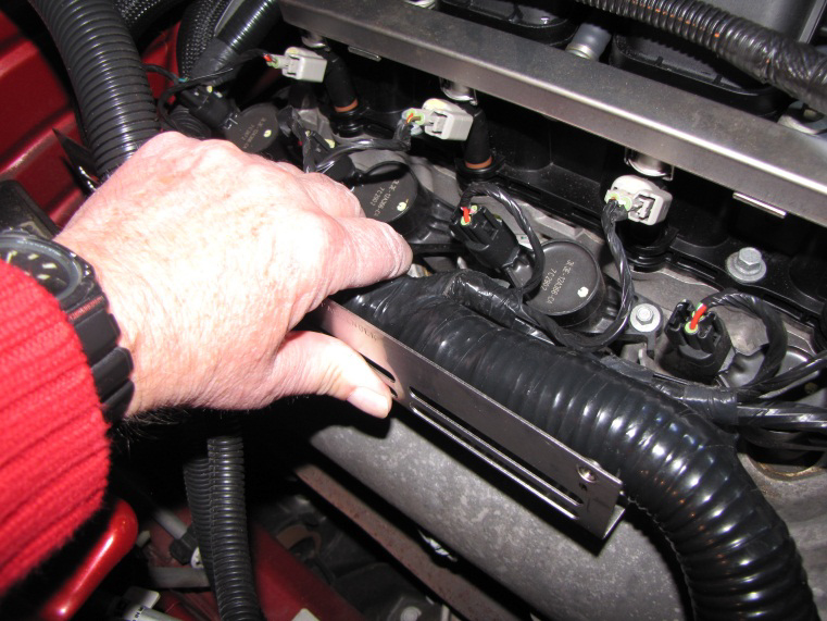
Figure 11
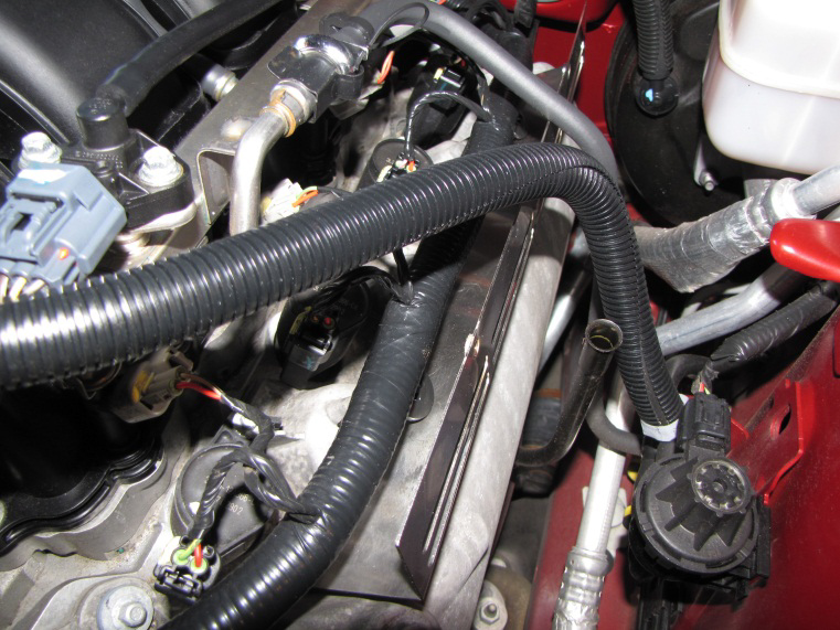
Figure 12
Identify the two mounting studs –Fig 13 on the passenger side intake manifold and pull the jam clips off the studs. Remove the studs using an 8mm socket –Fig 14. Be very careful not to drop the studs or move the fuel rails.
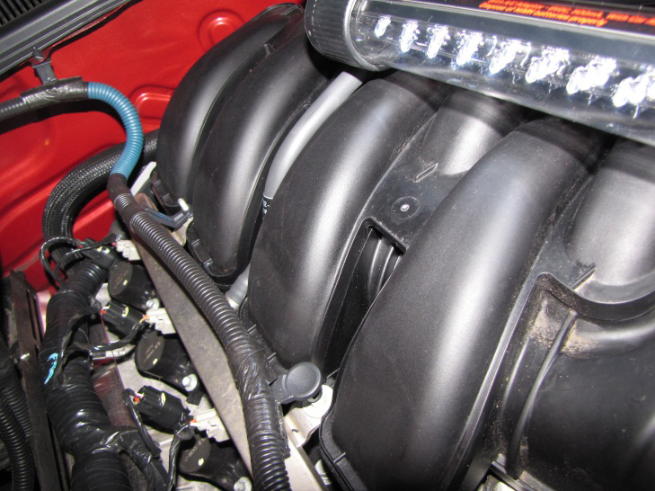
Figure 13
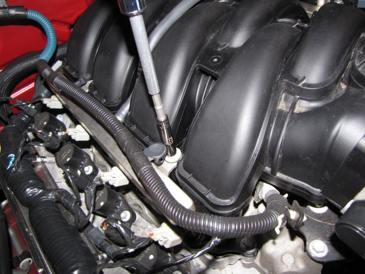
Figure 14
Install the passenger side fuel rail cover (it has two mounting tabs) by aligning the holes on the cover with the threaded holes on the outside of the stainless bracket. Attach the passenger side cover using two 10-32x3/8” screws and the supplied Allen wrench –Fig 15. The threads are fairly small so be careful not to cross thread them. Next, align the mounting tabs over the intake manifold threaded holes and then reinstall the studs –Fig 16. Do not over tighten the studs as the cover is made of a composite that can crack if the studs are over-torqued.
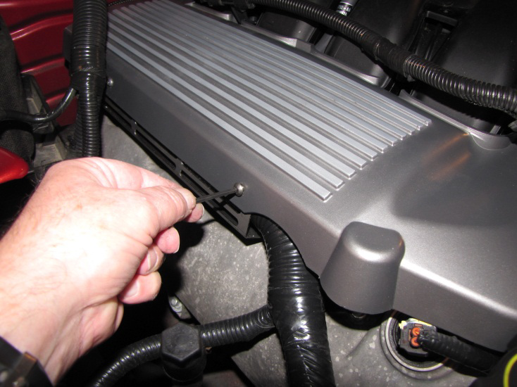
Figure 15
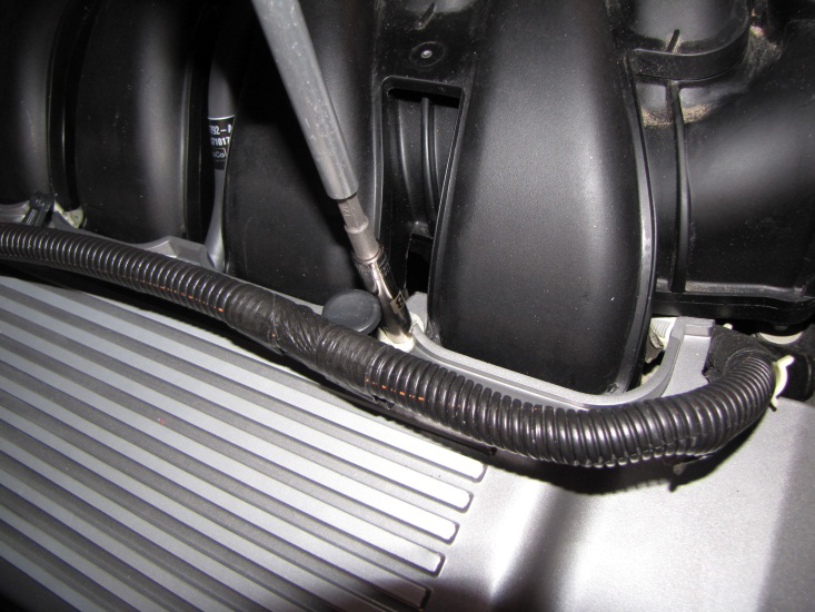
Figure 16
To install the driver’s side fuel rail cover, several more things must be moved out of the way. Disconnect the mass air sensor harness by sliding the red tab towards the firewall and pulling the harness connectors apart –Fig 17. The air box and duct must be removed by loosening the clamp closest to the throttle body with an 8mm socket and disconnect the vent hose from the air duct by pushing on the green locking tab –Fig 18. Unfasten the air box by removing the bolt on the fender using a 10mm socket –Figs 19 & 20. Remove the entire air box and duct assembly and set them aside.
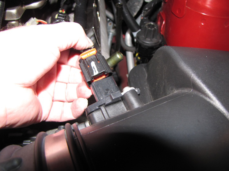
Figure 17
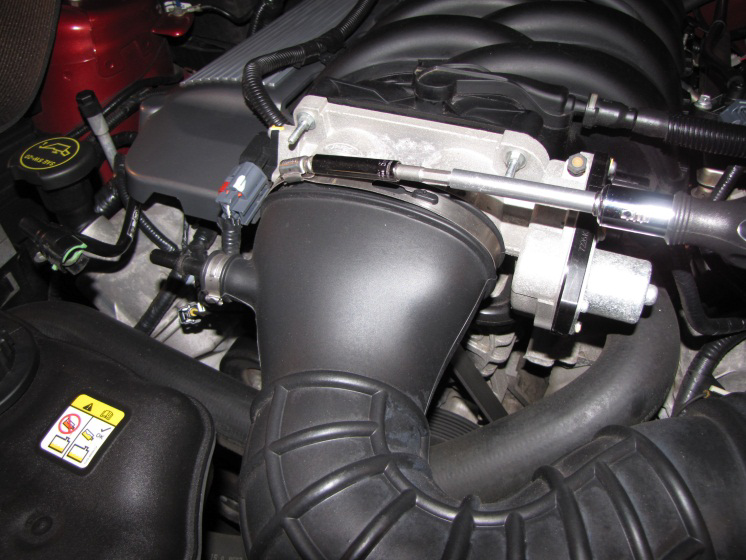
Figure 18
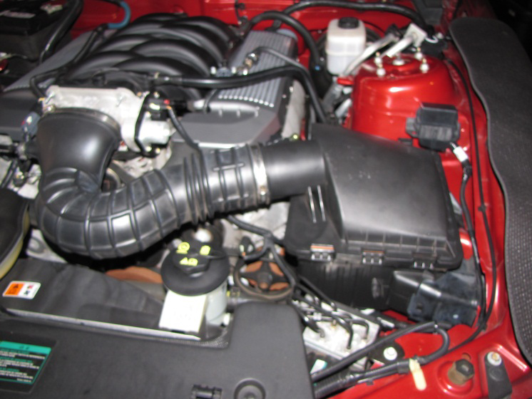
Figure 19
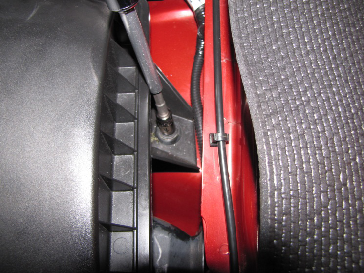
Figure 20
Rotate the fuel rail coupling clip to give the most clearance for the fuel rail cover –Fig 21. Do not remove any fuel lines! Locate the one stud on the driver’ side intake manifold and carefully remove it
–Fig 22.
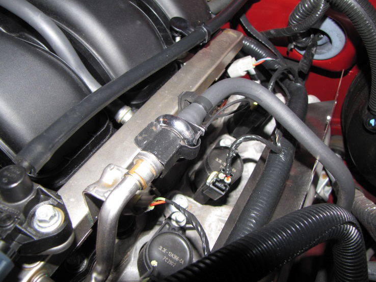
Figure 21
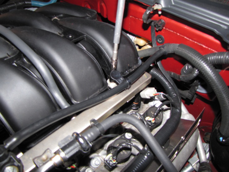
Figure 22
Very cautiously, slide the driver’s side fuel rail cover into place to align the two holes with the threaded holes on the bracket. It will take some maneuvering while pushing wires and hoses out of the way to position the cover correctly. Again, be careful not to scratch the cover. Repeat the same attachment procedures as the passenger side (insert two 10-32x3/8” screws to attach the cover to the bracket –Fig 23) except only one stud is used to hold the cover to the intake manifold –Fig 24.
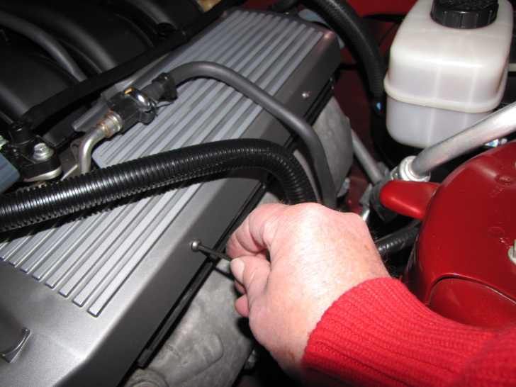
Figure 23
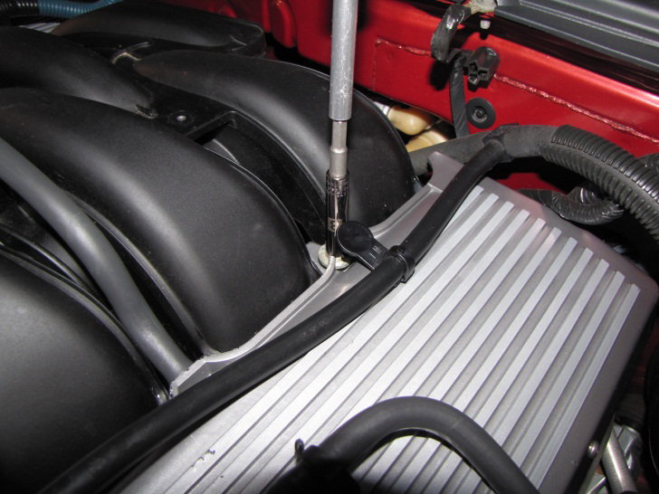
Figure 24
Finish the project by re-installing the air box and duct (be sure to re-connect the vent hose and mass air sensor on the duct). Re- install the vacuum hose and oil dip stick –Fig 25. Reverse the removal procedure for the plenum cover and secure it by replacing the three jam clips on the intake studs and the two nuts on the throttle body studs. Congratulations! The finished installation should look like –Fig 26.
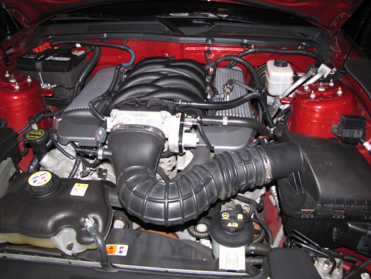
Figure 25
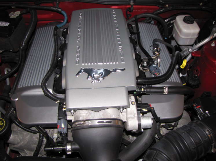
Figure 26
