 FREE 1 to 3-Day Delivery on Orders $149+ Details
Talk to a Mustang Sales Tech
1-877-887-1105
M-F 8:30A-11P ET, Sat-Sun 8:30A-9P ET
How to install a Hellion Single Turbo on your 2005-2010 GT Mustang
Installation
- Disconnect Battery
- Drain Radiator, keep fluid for re-installation.
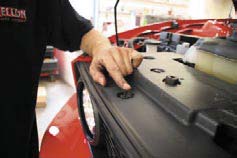
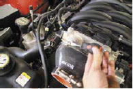
- Remove air box and inlethoses.
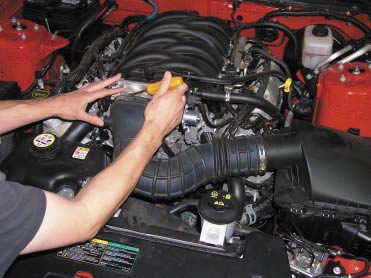
- Remove coolant overflow tank and hose.
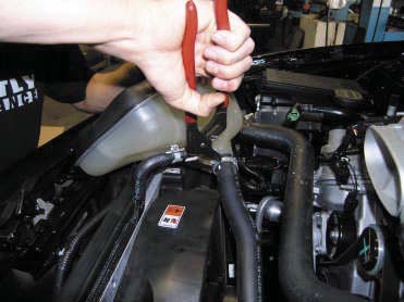
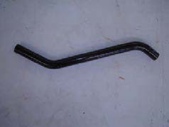
- Remove upper radiator hose. This hose will be cut and used later.
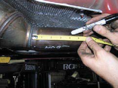
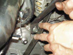
- Next, underneath, punch oil pan for turbo oil return. Mark a spot 5/8 inch down from the pan rail, and ¾ inch in front of the fi rst bolt on the driver side of the oil pan. Punch pan with supplied punch until seated. Remove punch, and tap with supplied 3/8 inch tap. Before tapping, coat tap with grease to catch any shavings. Use 5/8 12pt socket and ratchet. Apply pressure when turning tap.
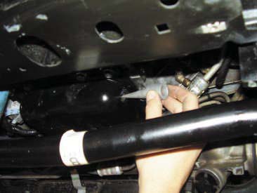
- Clean tapped hole, and install 3/8 to # 10 fi tting with silicone or Tefl on tape to seal threads.
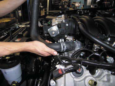
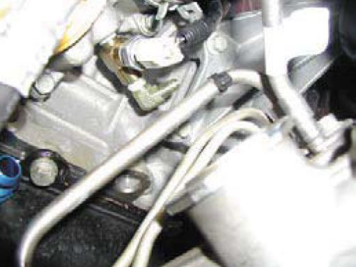
- Locate the oil pressure sensor on the driver side of the engine.
- Remove pressure sensor and set aside.
- Install supplied ¼ inch TEE fi tting into port with sealant.
- Install ¼ x #4 fi tting into TEE, and re install oil pressure sending unit into TEE.
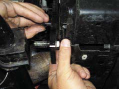
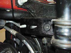
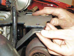
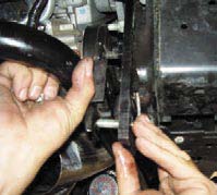
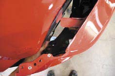
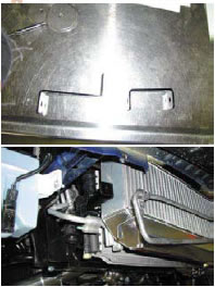
- Next, we need to unbolt the sway bar from the lower radiator support and remove lower sway bar studs.
- Now, install the supplied sway bar relocation brackets to the lower radiator support. Using the supplied 10mm fl at head bolts and the nut welded to the extension, secure the bracket to the support. The extension will allow the nut to be held behind the bracket. Use the factory nut to secure the top factory stud. Repeat on other side. Leave sway bar loose for now, as it will aid in installing the turbo piping. After piping is installed, sway bar and brackets will be installed.
- If using the Race Pipe option, install pipes with supplied 2.5 in clamp, and skip to step #23. Leave all clamps and piping loose until fi nal installation.
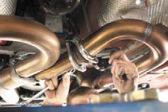
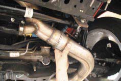
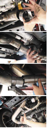
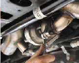
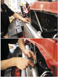
- The next step is to cut the factory H pipe to install the turbo piping.
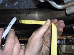
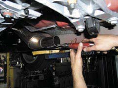
- Using a saw, cut the passenger pipe 4 inches behind the factory cat to pipe weld.
- Next cut the driver side pipe 3 inches behind the fi rst bend after the factory cat.
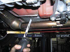
- Remove remaining rearward section of H pipe
- Remove all burrs.
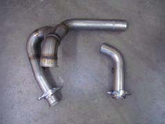
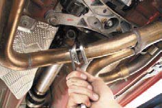
- Install pipe HT 1 with supplied clamp on driver side H pipe, leave clamp loose.
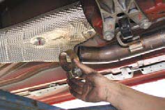
- Install pipe HT 8 with supplied clamp on passenger side H pipe, leave clamp loose.
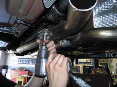
- Bolt these two pipes together using supplied 3/8 bolts and washers. Leave bolts loose. (The H pipe to manifold bolts may need to be loosened to assist installation.)
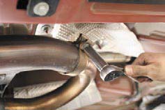
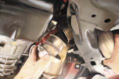
- Install HT 4 through hole in driver side K member, and connect to HT 1 or Race pipe with supplied V band clamp. Leave clamp loose.
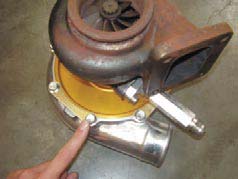
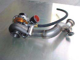
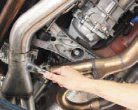
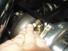
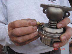
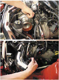
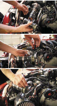
- Next clock turbocharger compressor and turbine housings as shown in picture. To do this loosen turbine and compressor bolts and rotate. Make sure to position oil feed up when clocking. Tighten all bolts.
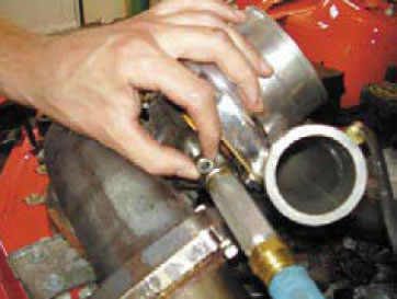
- Next install oil drain fl ange with supplied bolts and gasket. After tightened, install oil drain extension fi tting into drain fl ange using sealant.
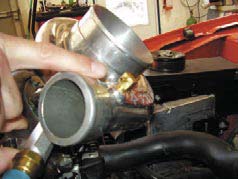
- Now, install 90 degree vacuum fi tting into port on compressor housing.
- Slide on the supplied 2.5 inch silicone hose over compressor discharge and secure with supplied t-bolt clamp.
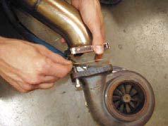
- Next, bolt turbo to HT 7 using gasket and supplied bolts.
- Now, assemble oil drain line by pressing the #10 push lock hose ends into the supplied oil return hose. Push hose until hose seats against plastic ring.
- Attach the oil drain line to the oil extension fi tting and tighten.
- Remove lower plastic front clip to radiator support cover
- To ease the fi rst intercooler pipe installation, install HT 9 into engine compartment. This pipe will fi t between the k member and the radiator shroud. You will need to unbolt the plastic AC line retainer to ease installation of this pipe. After installed, bolt AC retainer back using factory nut.
- Lower turbo assembly into engine compartment and fi sh piping towards underside of the car. Allow assembly to lay in engine compartment until we secure it to the turbo support bracket.
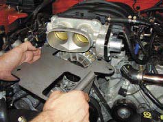
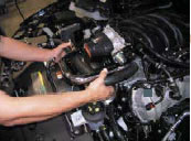
- Our next step is to lift the stock injectors and rails out of the way to make room for inner intake bolt access. The injector rails are secured with (4) 8mm bolts. *Larger injectors installed later.
- Locate the remaining 10 10mm bolts that retain the intake manifold. The intake needs to be raised to remove the alternator support bracket. The passenger side rear bolt will hit the intake if it is not raised. Once these bolts are loosened, remove alternator bracket and bolts. Leave intake loose, and replace the factory bracket with the new turbo support bracket and bolts. Install new injectors and tighten intake bolts to 89inch lbs.
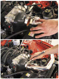
- Once installed, bolt turbo to bracket using supplied ¾ inch long 5/16 bolts. Remove (2) standard compressor bolts and use supplied ¾’ long 5/16 bolts.
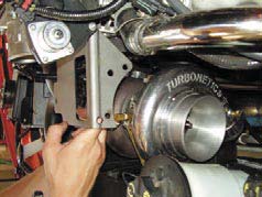
- Install supplied 2.5” T-bolt clamp over silicone hose on turbo & connect HT9 to Turbocharger. Tighten clamp.
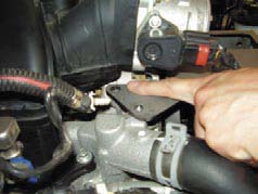
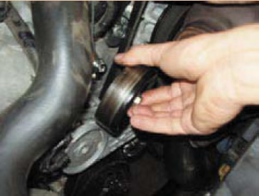
- Next, remove the passenger side idler pulley. Remove the adjacent timing cover bolt, install the turbo support bracket strap, and tighten using factory bolt.
- Now, bolt the turbo support strap to the support bracket using the supplied 5/16 bolt, washer, and nut. Reinstall pulley.
- Bolt the upper turbo inlet pipe (HT7) to HT4 pipe with the supplied v band clamp, leave clamp loose.
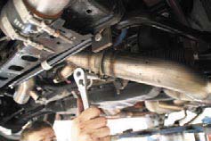
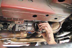
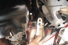
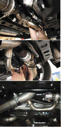
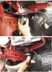
- Install HT 5 through passenger side k member hole.
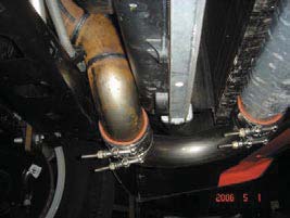
- Install downpipe HT5, sliding on supplied torq clamp fi rst, into (HT3) and secure using supplied v band clamp to the exhaust side of the turbo. Snug clamp, but do not tighten at this time. Push p/s lines up so they do not come in contact with the downpipe.
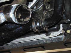
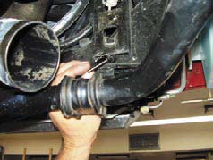
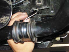
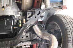
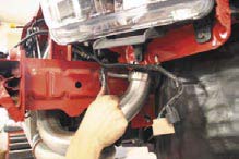
- Install HT2 with clamp onto HT5, sliding hanger into factory hanger holder.
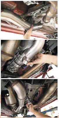
- Now install Y pipe, HT6, with clamp onto HT2 and connect to factory exhaust using factory clamps. (see next page)
- Put swaybar over studs and tighten nuts.
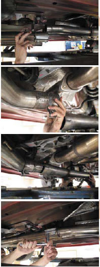
- Install wastegate, using supplied bolts and nuts, There is no gasket between wastegate and HT 7.
- Slide HT 16 into wastegate re-entry bung and bolt to Wastegate using supplied bolts and gasket.
- Attach supplied 1 5/8” clamp and tighten.
- Install 90 degree pipe fi tting into turbo using sealant.
- Connect #4 braided oil feed line from previously installed TEE to turbocharger. Route oil line away from moving parts and secure with supplied zip ties.
- Connect oil drain line to pan and tighten.
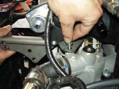
- Install supplied 1/8th pipe barb into the underside of the wastegate (SEE PIC). This is very important. The fi tting must be on the correct side for proper operation. An incorrect installation will over boost the engine.
- Take supplied vacuum line and connect hose from the turbo compressor fi tting to the underside of the wastegate. Secure vacuum line to oil line with supplied zip ties
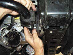
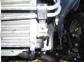
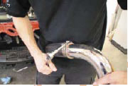
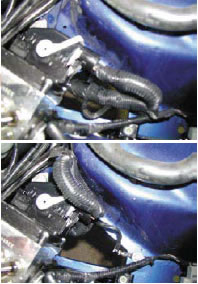
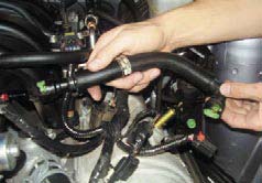
- Take the previously removed upper radiator hose and cut to splice in supplied pipe. Secure with supplied hose clamps.
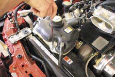
- The steel coolant can splice will need to be installed before coolant can reinstallation. Cut the factory rubber hose, leaving some length off of the end of the coolant tank to slide over the splice. Connect, and secure with supplied clamps.
- Wrap hose and end of tank w/ supplied heat wrap.
- Attach other end of coolant splice in engine compartment, securing with hose clamp.
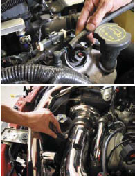
- Reinstall coolant can.
- Remove upper plastic radiator cover.
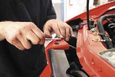
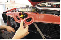
- Next, remove front fascia. Disconnect the plugs for the parking and lower lights.
- Remove the two 10mm headed bolts on the upper part of the grill.
- Remove the 6 philips headed screws holding the inner splash panels.
- Remove the (4) 10mm nuts holding the bumper cover to the fenders. (2) on each side.
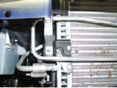
- Remove the two nuts that hold the P/S cooler line to the core support and let the cooler lines hang for intercooler installation.
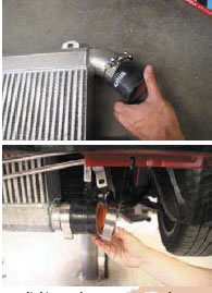
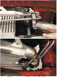
- Take intercooler and install 2.5 inch silicone hoses and clamps onto the intercooler inlet and outlet.
- Take supplied intercooler support straps and remove hood latch bolts, one at a time, and bolt strap to the core support. Do one at a time to ensure that the hood latch will remain the factory location. The long strap goes on the drivers side. Tighten both bolts when fi nished.
- Remove 2 splash guards on either side of radiator.
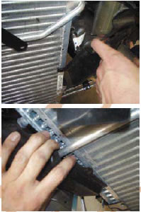
- Next, install the intercooler to the straps using supplied 5/16 bolts, washers, and nuts. (see next page)
- Bolt p/s line to supplied Z & U brackets using supplied ¼” x ¾” bolts, nuts and washers. Bolt brackets to factory location using factory bolts.
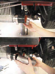
- Install intercooler pipe 2 (HT10) with silicone hose and clamps onto intercooler inlet and onto intercooler pipe 1. (HT9)
- Next install the long 7 inch silicone hose over polished intercooler pipe 4 and secure with a clamp.
- The long silicone hose will fi t through the fender hole. The factory harness will need to be moved over to make room for the hose to push through. Enlarging the hole is an option, but not necessary.
- Next install intercooler pipe 3 (HT11) into long silicone hose and secure with clamp.
- Push other side into intercooler and clamp.
- Install oval throttle body hose onto polished pipe and connect to throttle body.
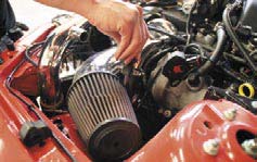
- Install 4 inch inlet pipe and air fi lter using supplied hose and clamps.
- Remove Mass air sensor from factory housing and install into polished pipe using supplied screws.
- Install air fi lter.
- Mass air wires may need to be extended if Mass air extender is not used.
- Install Bypass valve and tighten all clamps.
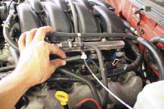
- Cut the vacuum line above the fuel rail and install the supplied TEE. Connect the supplied 7/32nd vacuum line from the bypass valve to the supplied TEE
- Cut off plastic tube from factory plastic 90 degree fi tting on passenger valve cover. Connect supplied 3/8” hose from 90 degree fi tting on valve cover to port on polished 4” inlet. Clamp using supplied 3/8” hose clamps.
- Remove driver side breather hose.
- Cut off black plastic tube ends from drivers side vent tube and assemble PCV assembly as shown using supplied hoses and PCV valve.
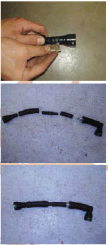
- Connect to engine once assembled and secure hoses with supplied hose clamps. 86. Position all turbo piping and tighten all clamps keeping piping away from touching surrounding metal and rubber. [The Hellion System is very adjustable and proper positioning is needed before clamps are tightened]
- Re-install front facia.
- Re-connect all lights.
- Fill radiator.
- Change oil and fi lter. We recommend using synthetic oil.
- Check all bolts, clamps and hose connections.
- Start car, checking for exhaust and fl uid leaks.
Take vehicle to a dyno facility and have the computer fl ashed to tune in the car.
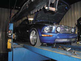
Putting the vehicle under boost without the proper programming will cause major engine Damage.

