 FREE 1 to 3-Day Delivery on Orders $149+ Details
J&M Mustang Adjustable Upper Control Arm ('05-'10) - Installation Instructions
Installation Time
4 hours
Tools Required
- Torque Wrench (Capable of at least 130 ft/lbs)
- Socket Wrench
- Socket Extensions (A Couple Around 4 and 12 Inches)
- 18mm Socket
- 21mm Deep Socket
- 18mm Wrench
- Jack
- Jack Stands
- Magnetic Angle Finder (f You Need To Adjust Pinion Angle)

Shop Parts in this Guide
Installation
1. You’ll want to jack the car up first, and set it on jack stands. The vehicle’s suspension should “be loaded”, so place the rear jack stands under the rear axle. This loads the suspension in the same manner as when the car is resting on its wheels. It’s not necessary to remove the rear wheels, but it may help you in accessing the rear of the upper control arm. So I’d suggest removing them. So with the parking brake set, and the vehicle in gear, loosen the rear lug nuts and remove the two rear tires. Then release the parking brake.
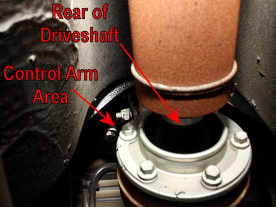
2. Begin the removal process by locating the upper control arm. It’s located in the area just above the rear of the driveshaft, between the car’s floor pan and the driveshaft.
3. Start by loosening the nut on the front control arm bolt, found on the passenger side of the control arm. The nut requires a 21mm socket, and a standard length socket should suffice. You will probably need to hold the bolt with an 18mm wrench to keep it from turning while loosening the nut. Place the nut to the side once it’s removed, you will not be able to remove the bolt just yet.
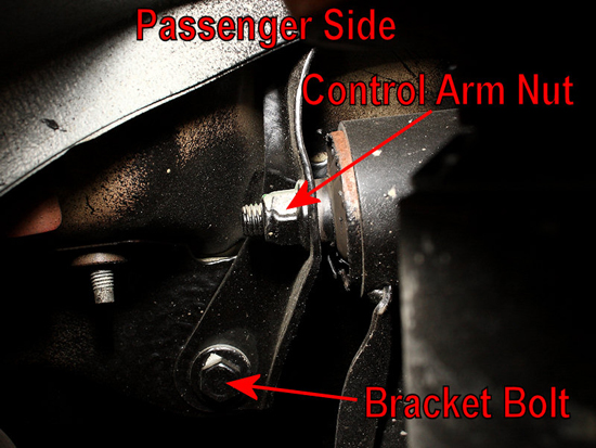
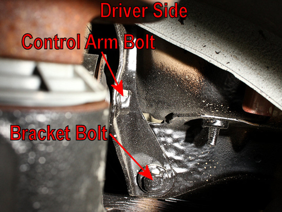
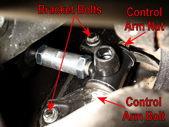
4. Locate the control arm bracket. It’s U-shaped, and sits at the front of the upper control arm. There are three bolts holding the bracket in place, one of which is hidden by the fuel tank and the other two on the driver and passenger sides of the driveshaft. Remove these two bolts with an 18mm socket and socket wrench. We’ll get the hidden bolt in a minute, from the inside of the car.
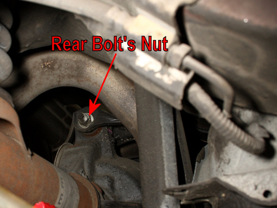
5. Now it’s time to focus on the rear of the control arm, where it attaches to the axle housing. The bolt can be seen above the rear differential housing, from the driver’s side of the vehicle. It is a flag bolt, which means it has a tab which will prevent the bolt from turning when the nut on the other side is removed.
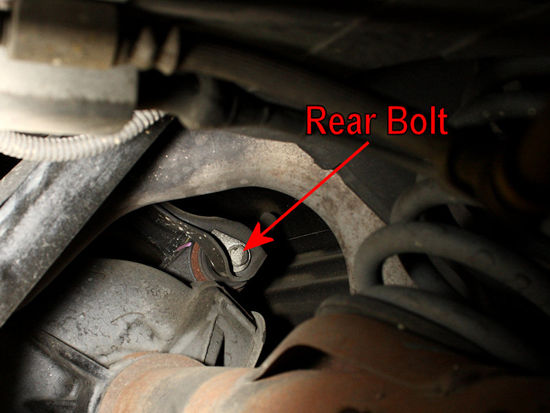
6. From the passenger side, access the nut on the bolt. You’ll need a 21mm deep socket to break it loose. You’ll also find your socket extensions useful in getting the proper clearance for the socket wrench as well. This is where removal of the rear tire helps, as it provides you more area in which to work. Once the nut is removed, remove the bolt as well.
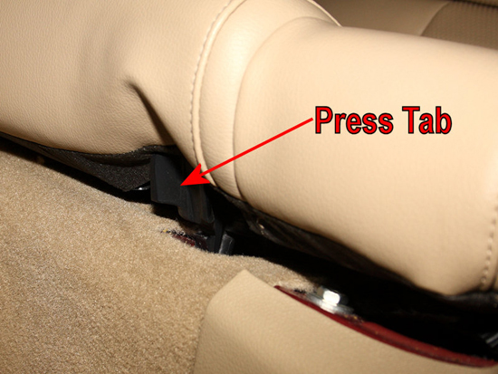
7. Next, climb out from under the car and prepare to take out the rear seat. There are two tabs located close to each end of the seat bottom. Push these tabs in, and the seat should easily pull up, allowing you to remove it from the car.
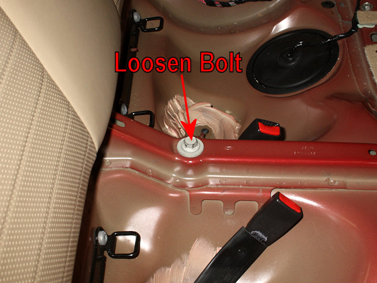
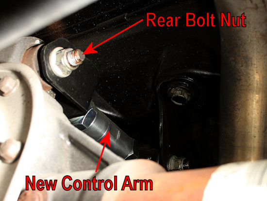
8. You’ll find a bolt positioned on the driveshaft tunnel of the car. Use a 21mm socket and socket wrench to loosen this bolt. You can remove the bolt, but it isn’t necessary. Once this bolt is loosened enough, and the rear of the controlarm lifted away from the differential, you should be able to pivot the control arm bracket to remove the front control arm bolt you couldn’t remove earlier.
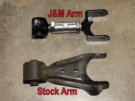
9. Once you remove the front control arm bolt, the stock arm should be able to be removed. A quick side by side comparison shows you the differences between the J&M Arm and the stock arm. Adjustability is offered by the center link on the J&Munit.
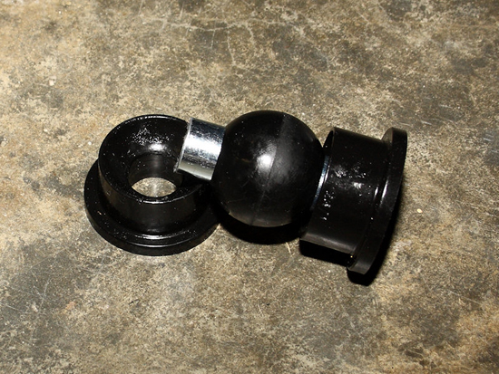
10. Familiarize yourself with how the bushing assembly fits together before you grease and install it. The bushing components will be used on the forward end of the upper control arm. The rear of the arm will use the factory components on the differential. When installed, the bushings for the front will be pushed together, but I’ve left them separated for clarity purposes in the picture below.
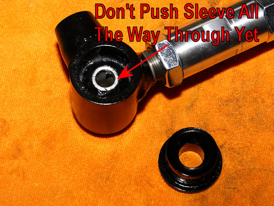
11. Upon assembly, you’ll also want to apply some of the supplied grease to the inside of the control arm as well as the bushings and steel sleeve. Once that’s done, press the bushing assembly into place from one side of the control arm. Before pushing the other side’s bushing into place, I found it’s best to push the steel sleeve halfway out of the installed bushing. This helps to allow air between the bushings to escape, and helps the remaining bushing to seat easier. Once the bushing is in place, you can push the steel sleeve in fully.
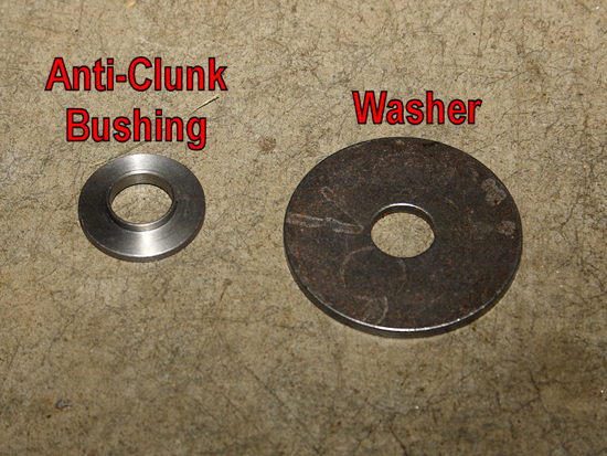
12. The J&M upper control arm makes use of a special anti-clunk bushing to help take up the slack between the bolt and the hole in the bracket. The difference in sizes can contribute to a clunking sound in the rear of the vehicle, even if the stock control arm is still installed. The anti-clunk bushing solves this issue. The standard washers are used to take up slack between the control arm and the bracket.
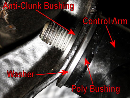
13. As shown below, use a washer between the control arm and the bracket. The anti-clunk bushing should be installed from the outer side of the bracket, and its smaller side will fit into the bracket’s hole. Repeat this procedure for both the driver and passenger sides of the control arm. I will point out that it’s a tight fit to get both washers in place, but with a little perseverance you’ll get them installed and everything lined up.
14. Thread the nut on by hand to hold everything in place. Then use an 18mm socket and socket wrench to tighten the bracket bolts back down. Use a torque wrench to get them tightened down to 85 ft/lbs. Then head back to the inside of the car, and tighten down the bolt that was loosened earlier back down. It should be torqued down to 129 ft/lbs. You can replace the rear seat once the bolt is tight. Next, you’ll want to torque down the front control arm bolt you hand-tightened earlier. It should also be torqued down to 129 ft/lbs.
15. All that’s left is to replace the rear control arm bolt and nut. The flag on the bolt doesn’t have anything to catch onto with the J&M upper arm, so you’ll need to use an 18mm wrench to hold the bolt while you tighten the nut with a 21mm deep socket and socket wrench. Torque specification for the rear bolt is 129 ft/lbs.
6. Once you remount the tires and wheels, if you’ve removed them, you’re ready for a test drive. If you hear anything unusual, recheck the torque of your bolts. Take note that due to the polyurethane bushings, you may see a slight increase in noise transmitted through the suspension to the interior of the car. The factory rubber bushings isolate this noise better than the polyurethane does. So it’s a trade off of sorts, getting a firmer suspension in exchange for a slight increase in noise.
One Final Note
I also want to point out, that the Ford Service Manual states that the bolts and nuts that connect the suspension arms to the vehicle should not be reused. With that being said, I know many mechanics that insist that reusing the bolts is fine, providing the threads appear to be undamaged upon inspection. Personally I’m not about to enter that debate, and you can choose your own course of action when it comes to replacing the bolts. However, for those that wish to do this, I’mproviding the Ford part numbers below. This should prove useful when you arrive at the parts counter. Be prepared to pay in the neighborhood of $4 for each bolt, and around $3 for each nut.
I should also point out that the bolt and nut that connect the bracket to the upper control arm isn’t sold individually. It’s only available as an assembly with the stock bracket and control arm. The part number for the entire assembly is5K671.
Here is the part numbers for the other hardware (Only 1 of each item is needed unless specified otherwise):
- Upper Control Arm Flag Bolt:W710051-S439
- Upper Control Arm Nut:W520215-S440
- Upper Control Arm Front Bracket Bolt:W708795-S439
Upper Control Arm Rear Bracket Bolt:W709884-S440 (Quantity 2)
Installation instructions provided by AmericanMuscle customer Eric Hege 4.29.09
Related Guides
-
Installation
-
Installation
-
Installation
