 FREE 1 to 3-Day Delivery on Orders $149+ Details
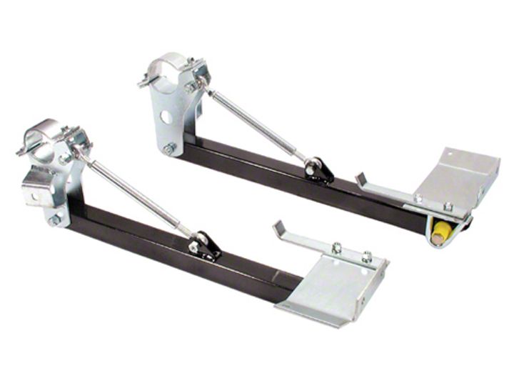
Lakewood Mustang Traction Bars ('79-'95) - Installation Instructions
Installation Time
3 hours
Tools Required
- (1) Axle mounting bracket-left
- (1) Axle mounting bracket-right
- (2) Brake limiter loop
- (2) Axle clamp-upper
- (1) Frame rail reinforcing plate-left
- (1) Frame rail reinforcing plate-right
- (2) Mounting strap
- (2) Link connector
- (1) Hardware kit
Shop Parts in this Guide
Installation
Removal:
1. Place car on solid level surface such as a garage floor to insure safe installation.
2. Use wheel chocks or 4" x 4" wood block is front of and behind both front wheels.
3. Jack rear end of car up and place jack stands under rear control arms behind coil springs. Lower car onto jack stands. Rear wheels should be approximately 1" off ground:
4. Installation of traction bars is performed one side at a time. Remove one rear wheel.
Note:Before working underneath car be sure that it is securely stabilized on jack stands to avoid any possibility of bodily injury.
5. Remove rear lower control arm nut and place a hydraulic jack under the inside portion of the lower control arm directly below the coil spring. Jack the control arm up just enough to free lower control arm bolt. Tap bolt out carefully with a mallet. Be very careful not to damage bolt threads. This is a metric bolt (11 mm) and must be reused.
Note:On some cars the rear stabilizer bar will have to be permanently removed if there is not adequate clearance between the stabilizer and traction bar mounting brackets. Check for clearance when installing traction bars.
6. Install traction bar mounting bracket under axle housing against lower control arm bracket(Note: There are right and left side brackets).Reinstall factory lower control arm bolt through traction bar mounting bracket hole, then through factory housing bracket and lower control arm. Attach factory nut finger tight.Carefully install axle clamp over housing and under brake lines.Secure with 7/16” x 1 ¼” bolts, washers and nuts supplied (see illustration). Tighten lower control arm bolt and axle clamp bolts at this time.
7. Install rubber snubber in hole at front of traction bar using 3/8” lock washer and nut supplied. Assemble brake limiter bushing on inside of bar using ½”x 3 ½” bolt, flat washer and self-locking nut (see illustration).Urethane bushing flange must be facing inward toward the center of car. Tighten bolt snug against urethane bushing (crush bushing just slightly). Insert rear of traction bar into axle mounting bracket with snubber touching the floor pan and secure with½”x 2 ¾” bolt and nut supplied.
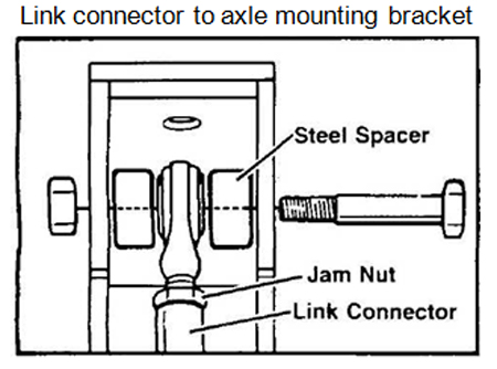
8. Assemble link connector with rod ends and jam nuts. Thread the rod ends in equally and adjust for proper length. Place spacer on either side of rod end in mounting bracket (see illustration), and attach link connector assembly to mounting bracket and traction bar using ½ ” x 2 3/4" ½” x 1 ½” bolts supplied. Tighten rod end jam nuts against link connector.
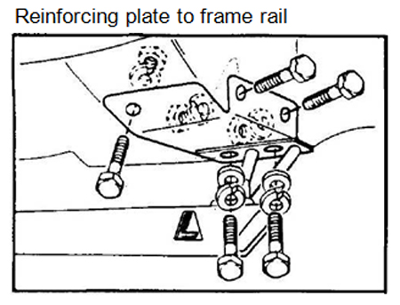
9. Install rear sub-frame reinforcing plate, mounting strap, and brake limiter safety loop as follows:(Note: There are right and left side reinforcing plates).Insert mounting strap through oval hole on inside of frame re-align threaded holes with factory holes in bottom of frame rail. Place reinforcing plate between snubber and frame rail (see illustration), align holes with mounting strap and frame rail holes. Position brake limiter safety loop around urethane bushing and up against reinforcing plate, align with mounting holes. Thread 3/8” x 1" bolts with flat washers and lock washers through holes into mounting strap finger tight. Align brake limiter safety loop with brake limiter urethane bushing by sliding bracket forward or rearward. Three (3) 3/8” holes must also be drilled through frame to attach reinforcing plate. Lift reinforcing plate up against frame, use the plate as a template and drill through hole in the side of plate that is facing the outside of frame. Insert bolt, fasten with lock washer and nut. Drill remaining two (2) holes through front section of reinforcing plate, insert bolts, fasten with lock washers and nuts. Tighten all bolts securely.
10. Reinstall wheel and tighten securely. Repeat above procedure on opposite side to install other traction bar.
11. Check rubber snubber gap. Do not attempt to level the car with rubber snubber (snubber touching reinforcing plate) as it will cause radical preloading and considerable torque steer problems for street applications.
12. Adjust rubber snubbers to desired position. This is done by adjusting the link connector length, move upper and lower rod ends equally in or out to attain proper length. ½” gap on passenger side and 5/8” gap on driver side(clearance between snubber and reinforcing plate) works well on street/strip applications. For competition use, the air gap can be reduced depending on how the car reacts. If more travel is desired rubber snubber can be cut down with a hacksaw.
Snubber height must be a minimum of 1" thick.
13. The car can now be road tested for proper operation. Rear suspension travel will be limited and braking should improve. Wheel hop will be eliminated on hard acceleration. Periodically check and make sure all bolts and nuts are tightened securely.
Note:It may be necessary to readjust rubber snubber air gap after car is road tested.
Installation instructions provided by Lakewood

