 FREE 1 to 3-Day Delivery on Orders $149+ Details
How to install Maximum Motorsports Full Length Subframe Connectors on your Mustang
Installation Time
3 hours
Tools Required
- Standard Hand Tool Assortment
- Disk grinder/Sander
- MIG Welder
- 4 Jack Stands or Drive-on Lift

Shop Parts in this Guide
Congratulations on purchasing Maximum Motor-sports' new and improved Full-length Subframe Connectors. MM created the first full-length sub-frame connectors (We even coined the name) many years ago to provide more chassis stiffening than any other subframe connector available. We have now improved on our previous design with an even stiffer Full-length Subframe Connector. These have a taller tube for increased bending strength, and are longer to provide increased weld area and better support to the rear subframe. Once again Maximum Motorsports leads the way with better engineering and design.
Read all instructions before beginning work. Following instructions in the proper sequence will ensure the best and easiest installation.
Required Supplemental Items
• 3M or SEM Weldable Zinc Primer (available through your local automotive paint store)
• Spray Paint/Primer
Supplemental Installation Notes
• These instructions are universal for all 1979-04 Mustangs. Steps specific to certain model years will be indicated accordingly.
• All welding must be done with a MIG welder.
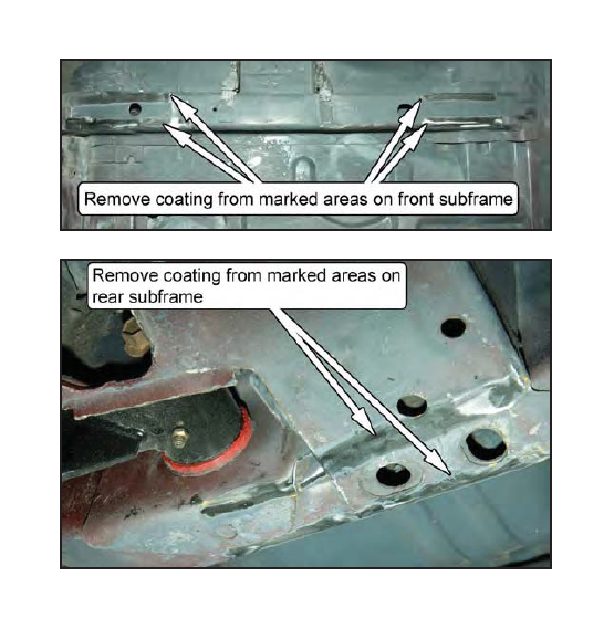
• The car's weight must be on the tires or supported with jack stands positioned on the rear axle housing and k-member.
• Clean all areas to be welded down to the bare metal for the best welding results. This includes the Subframe Connectors if they are powder coated.
• You may And that the floor pan and/or frame rails of your Mustang were bent upwards because of previous improper use of a jack, especially near the rearward mounting bolts for the front seats. If necessary, remove the seat(s) and pound the bent area(s) down, using your foot or a rubber mallet.
• The Subframe Connectors and chassis frame rails must be coated after welding to prevent rusting.
This Kit Contains
| Description | Qty |
|---|---|
| Subframe Connector, Driver | 1 |
| Subframe Connector, Passenger | 1 |
| Seat Brace, Driver | 1 |
| Seat Brace, Passenger | 1 |
| Reinforcing Plate | 2 |
| 7/16G8 Washer | 8 |
| 10mm-1.5 NylockNut | 4 |
| 10mm-1.5 x 35mm Bolt | 4 |
| Installation Instructions | 1 |
Installation
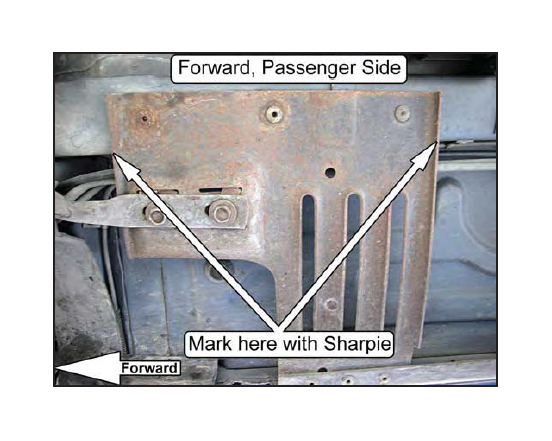
1. 1983-93CONVERTIBLE ONLY, ALL OTHERS SKIP TO STEP 12.
Using a Sharpie or other marking device, mark the front and rear edges of the front factory reinforcement plates where they first touch the factory subframe. These marks will be used in Step 10to determine how narrow the factory reinforcements must be cut.
NOTE: The MM Full-length Subframe Connectors must rest flat against the bottom ofthe factory subframe. In orderto do this, the portion ofthe front factory reinforcement plates that touch the front subframe must be removed.
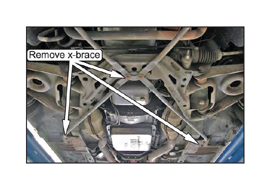
2. Remove the six bolts holding the rearward portion of the factory X-brace to the vehicle and remove the brace.
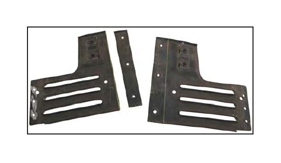
3. Using a drill bit or die grinder, remove the rivets retaining each of the front factory reinforcement plates to the vehicle.
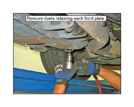
4. Remove the front factory reinforcement plates from the vehicle.
NOTE: Mark each plate to indicate which side ofthe vehicle the plates were taken from, and their original orientation, as they must be reinstalled in the same location.
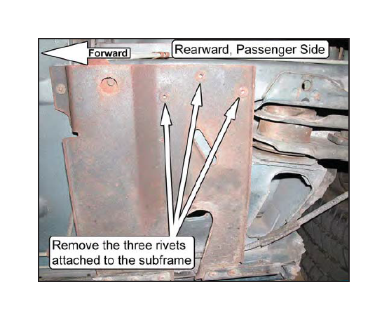
5. Using a drill bit or die grinder, remove the rivets retaining each rearward factory reinforcement plate to the factory subframe. Only remove the rivets that are in the subframe.
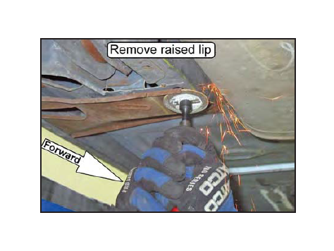
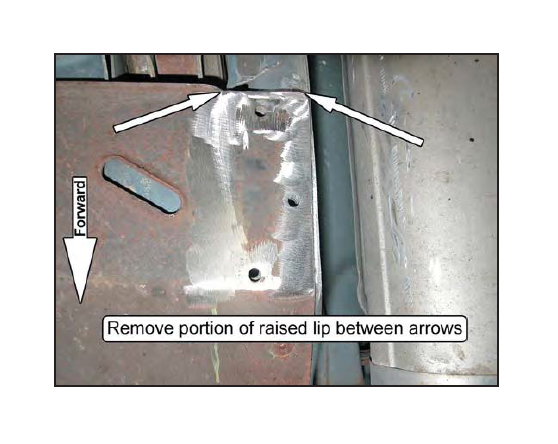
6. There is a raised lip on each rear factory reinforcement plate that is perpendicular to the centerline ofthe vehicle. This raised lip is directly in front of the opening for the rear lower control arm mount. The portion of this lip that lies below the factory subframe must be removed or flattened so that the MM Full-length Subframe Connectors can rest flat against the bottom of the vehicle. Using a hammer or grinder, make the lip flush with the surrounding factory reinforcement plate surface.
(Driver Side Shown)
(Driver Side Shown)
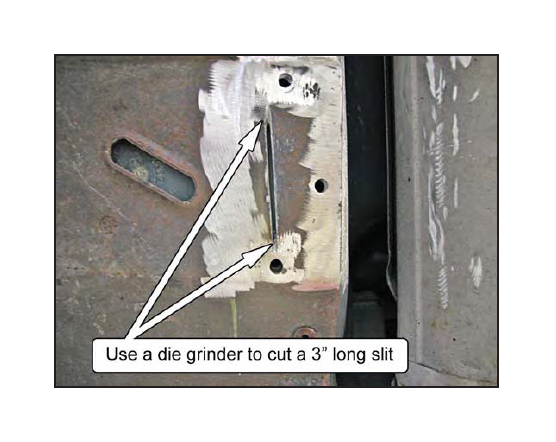
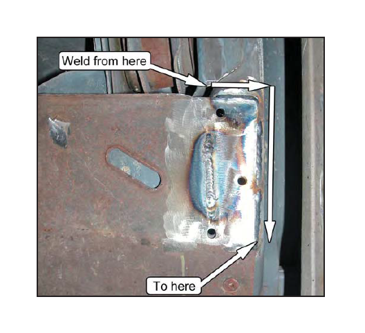
7. Using a grinder, cut a 3/16" or wider slit approximately 3" long in each of the rear factory reinforcement plates. This slit should be parallel to and directly below the outboard corner of the factory subframe. Be sure the slit goes all the way through the rear factory reinforcement plates.
NOTE: The purpose ofthis slitis to allowthe rear factory reinforcement plates to be welded to the rear factory subframe. By welding the rear factory reinforcement plates to the factory subframe along multiple points, the strength ofthe chassis will be increased.
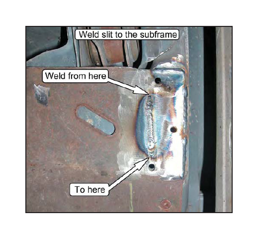
8. With the reinforcement plate pressed firmly against the bottom of the factory subframe, weld along all contacting areas.
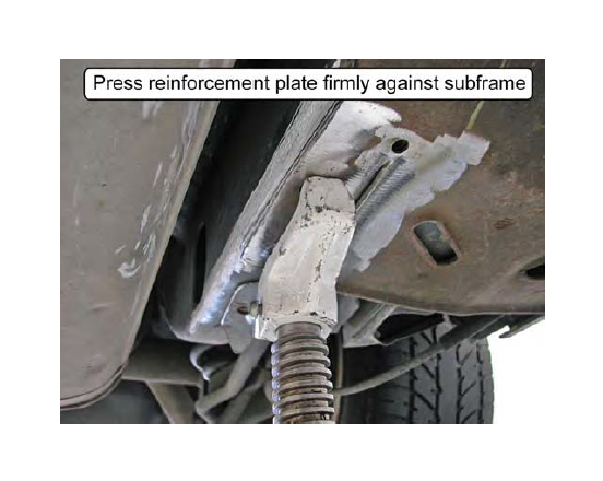
9. Weld through the slits made in Step 7 to the factory subframe.
10. Beginning with the driver side factory reinforcement plate, align a rulerwith the marks made in Step 1 and draw a straight line connecting the two points. Repeat for the passenger side factory reinforcement plate.
11. Using a hacksaw or other cutting device, cut along the lines drawn in the previous step to trim the factory reinforcement plates to size. Discard the smaller sections that have been cut away.
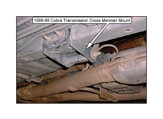
12. 1996-98 COBRA ONLY, ALL OTHERS SKIP TO STEP 13:
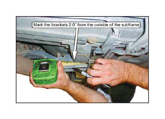
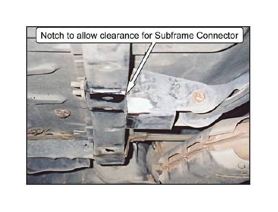
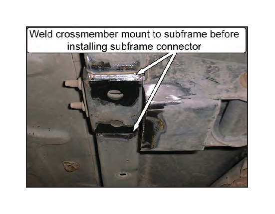
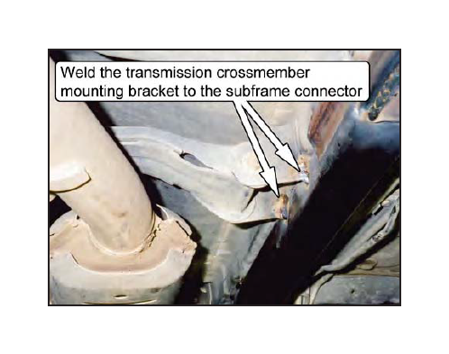
Notch both the passenger side and driver side transmission cross member mounting brackets so that the subframe connector will sit into position underneath the car's front subframe, as detailed in the steps below. The notch should only be large enough to allow installation of the subframe connectors. Once notched, we recommend welding the mounting brackets to the subframe for extra strength.
Positioning the Subframe Connector
13. Hold the subframe connector up against the bottom of the car, underneath the front and rear subframe of the car.
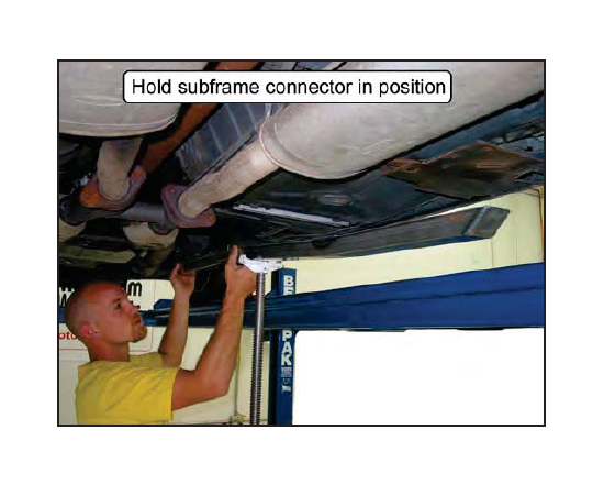
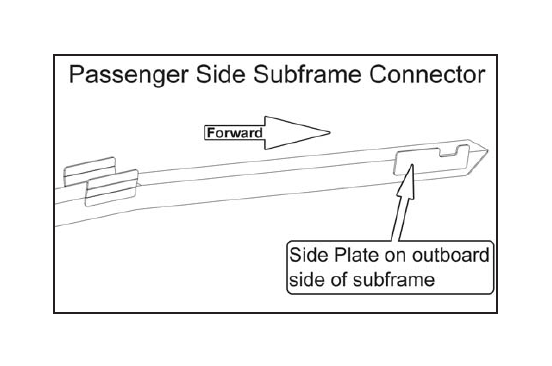
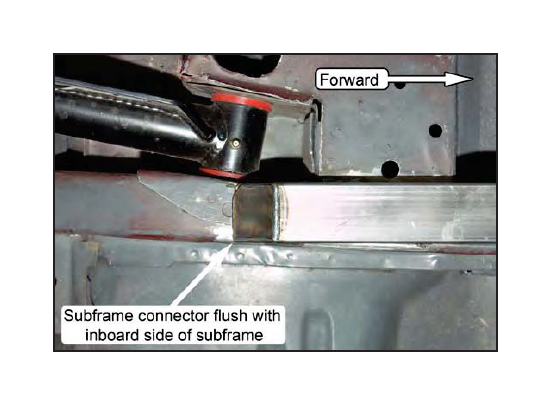
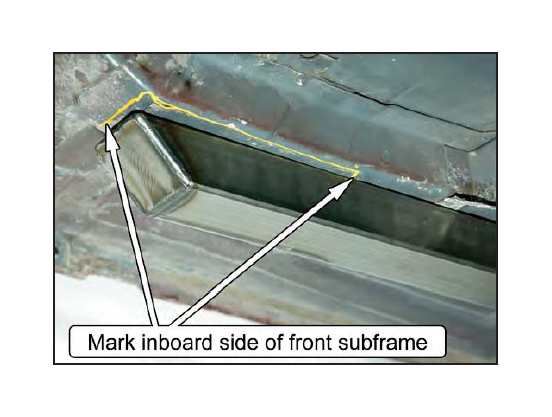
NOTE: The connectors fit specific sides. The forward end ofthe subframe connectortube has a Side Plate, which is to be positioned on the outside ofthe front subframe.
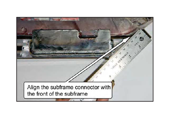
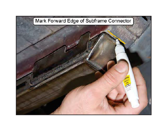
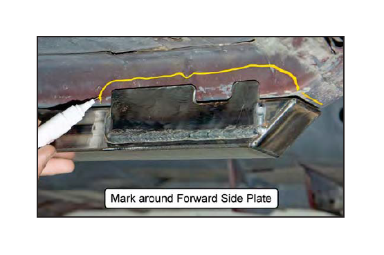
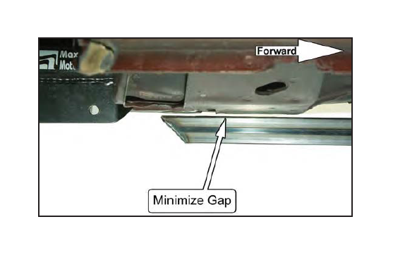
14. Place a straightedge on the front subframe connector end-cap, extending above the top surface ofthe connector by about 1". Use the straightedge to align the front of the subframe connector with the car's front subframe, where the front subframe angles upwards. This sets the fore and aft position of the subframe connector. Mark a line along the forward edge of the end cap to mark the correct position.
15. Push the front of the subframe connector towards the center of the car, so that the Forward Side Plate is tight against the outboard side of the car's front subframe.
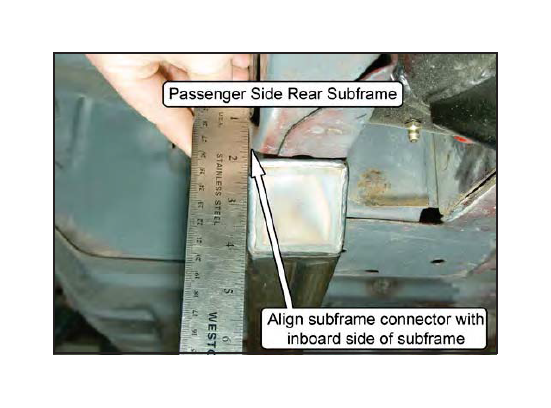
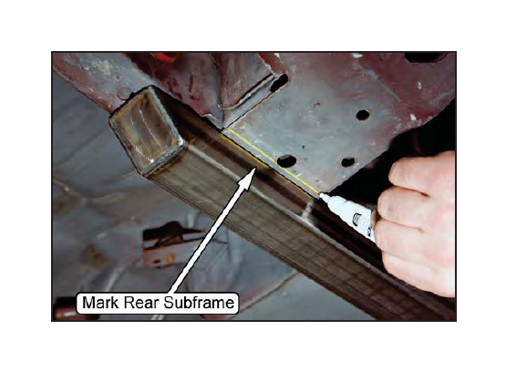
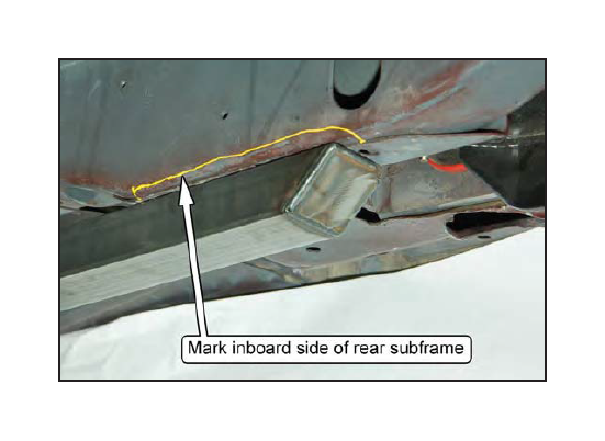
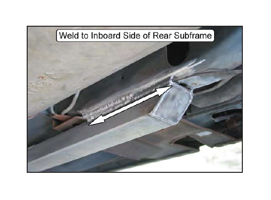
16. The rear of the subframe connector is to be positioned with the inboard side of its end aligned with the inner side of the car's rear subframe. This positions the subframe connector directly underneath the car's rear subframe, and provides the most clearance for the muffler.
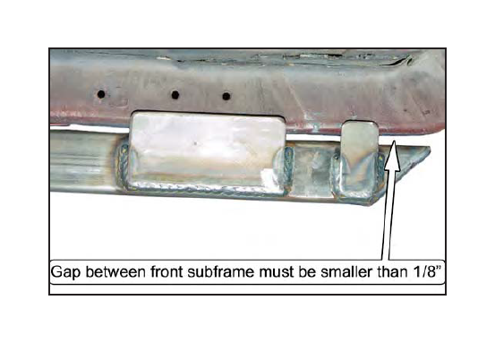
17. Check how closely the subframe connector fits to the underside of the car's front subframe. A gap of no more than 1/8" is acceptable.
NOTE: Ifthe car has been previously lifted up with a floorjack placed improperly underneath the front subframe, the floorpan may be distorted, causing a gap at the rearward end ofthe front subframe.
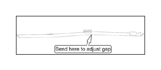
18. If there is a gap between the car's front subframe and the subframe connector at its front end, the subframe connector tube needs to have its forward bend straightened. Very small changes in the bend angle will have a large effect on the gap. The subframe connector tube can have the bend angle straightened out slightly while off the car by careful use of a hydraulic press. If using a press, be careful not to crush the tube.
19. With the subframe connector held in the correct position (as described above), mark on the subframe every place that will be welded. If using powder coated subframe connectors, mark the corresponding area on the subframe connectors.
20. Remove any coating in the marked areas down to bare metal. A power disc sander works well for this.
NOTE: Failure to remove the coating will cause porosity in the welds and general difficulty in welding.
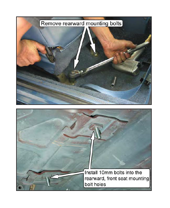
21. Remove the two factory rearward mounting bolts from each front seat and replace them with the provided 10mm bolts, using a washer underneath the bolt head.
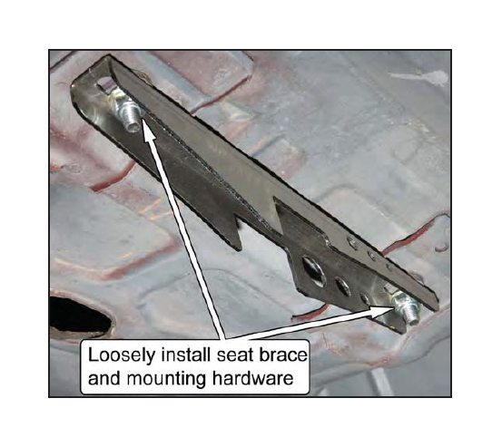
22. Loosely mount the seat braces to the bottom of the vehicle using the provided 10mm nuts. Make sure to use one of the provided washers underneath each nut.
NOTE: The seat brace should be able to move side to-side with a little bit of effort so that the subframe connector can be properly positioned.
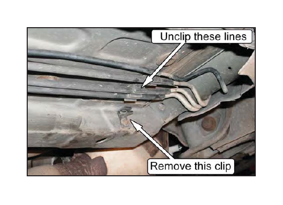
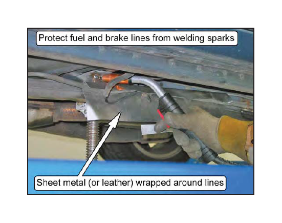
23. On the outboard side of the passenger side front subframe, remove any retaining clips that hold the brake and fuel lines in place. This will allow the lines to be pulled away from the subframe slightly during the subsequent welding steps.
NOTE: Some vehicles feature a plastic holder that allows the lines to be "clipped-in". Unclip the lines from these holders instead ofremoving the holder from the vehicle.
24. With the subframe connector again held in the correct position, tighten the seat brace mounting nuts.
NOTE: It may be necessary to have a helper in the vehicle hold a wrench on the bolts to stop them from rotating.
25. The seat brace may prevent the subframe connector from resting against the frame rail and cause a gap to form between the two. This gap should be reduced by pushing up the subframe connector directly below the seat brace.
NOTE: If a gap is present between the subframe connector and the seat brace, the floorpan will need to be pushed downwards to close the gap. This can usually be accomplished by having someone stand on the rear floor pan while tacking the subframe connector in position.
Welding the Subframe Connector
WARNING: Be careful to protect the fuel lines from heat andsparks during all welding operations.
NOTE: A fire extinguishershould always be accessible when welding on a vehicle.
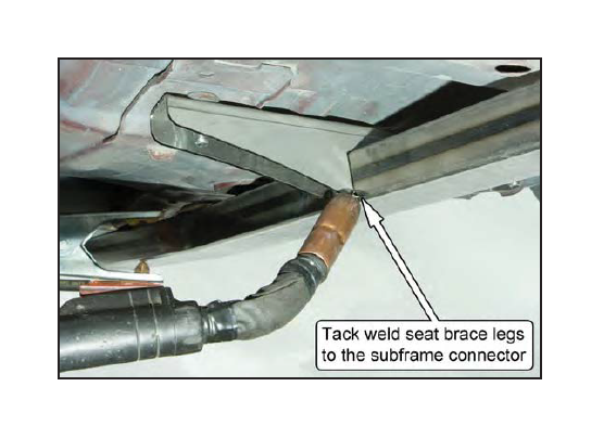
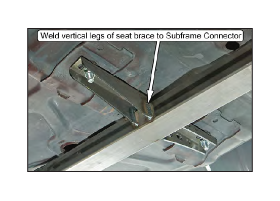
26. Tack-weld the four legs of the seat brace to the subframe connector.
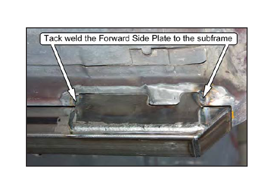
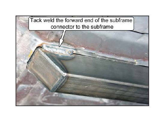
27. Tack-weld the forward end of the subframe connector in place.
28. Tack-weld the rearward end of the subframe connector in place. With the subframe connector now secured in place, double check that its position is correct. If necessary, remove the tack welds and reposition the subframe connector.
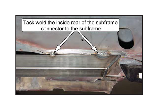
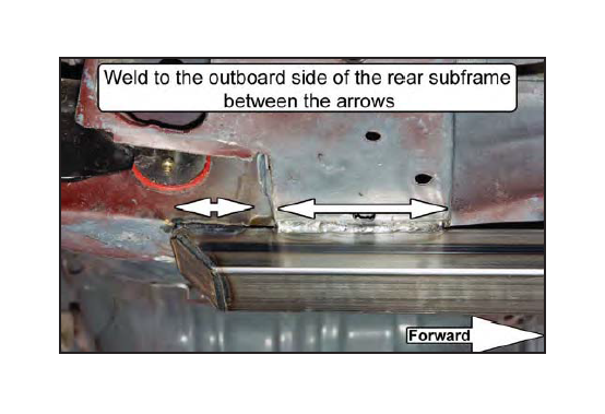
29. Weld the rearward end of the subframe connector into place. Weld where indicated in the photos.
NOTE: Do not weld across the end-cap, as doing so will create a heat-affected zone on the subframe that may later lead to cracking due to the orientation of the weld relative to the bending loads.
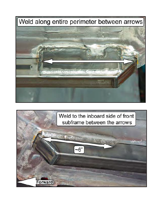
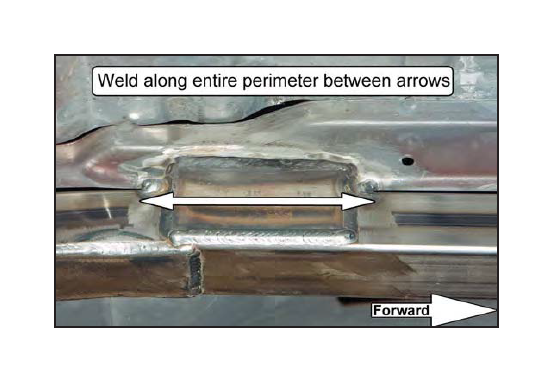
30. Weld the forward end of the subframe connector into place. Weld where indicated in the photos. Do not weld across the end-cap, as doing so will create a heat-affected zone on the subframe that may later lead to cracking due to the orientation of the weld relative to the bending loads.
NOTE: The slot in the Forward Side Plate ofthe subframe connectoris for 1994-04 cars. The slotis shaped to fit around a mounting bracket. Take care when welding this area to not damage the bracket mounting hole.
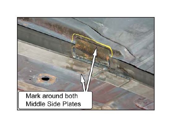
31. The two Middle Side Plates of the subframe connector tube will need to be custom-fitted into place against each side of the car's front subframe. This can be done by squeezing them with a C-clamp or large channel lock pliers, or by careful hammering. We position the plates to accommodate the range of tolerances in the placement of the front subframe on the floor pan, which requires the plates to be custom-fitted to the car during installation.
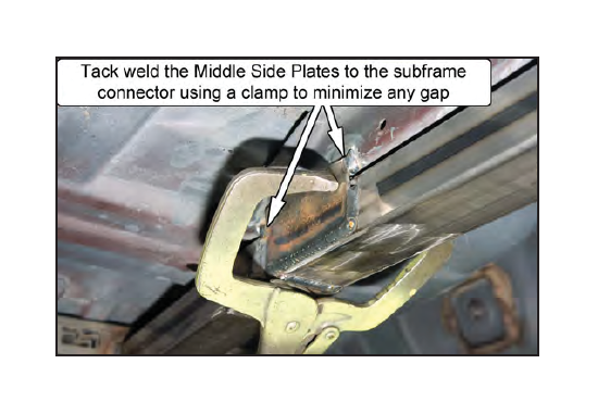
32. Weld the two Middle Side Plates to the car's front subframe, as indicated in the photos.
33. Weld the legs of the seat braces to the subframe connector. Make sure to wrap the welds around the ends of the legs.
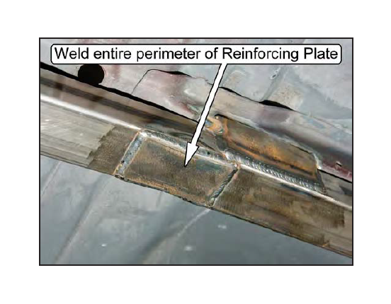
34. Locate the forward bend of the subframe connectortube. Place a supplied Reinforcing Plate against the bottom of the tube so it covers the bend area. Weld the entire perimeter.
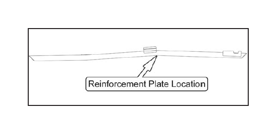
NOTE: If the subframe connector is powder coated, be sure to remove the coating from the area to be welded before welding.
35. Follow Steps 13-34 to weld the driver side subframe connector into place.
36. 1996-98 COBRA ONLY, ALL OTHERS SKIP TO STEP 37:
Weld the notched edges of the transmission crossmember mounting bracket to the subframe connectors.
37. If so desired, the subframe connector tube may be stitch-welded to the car's front subframe. Weld the corners of the subframe connector tube to the car's front subframe. A 1-inch weld every 3 inches is sufficient.
NOTE: Be sure to remove any coatings in the areas to be stitch-welded.
38. 1983-93 CONVERTIBLE ONLY, ALL OTHERS SKIP TO STEP 40:
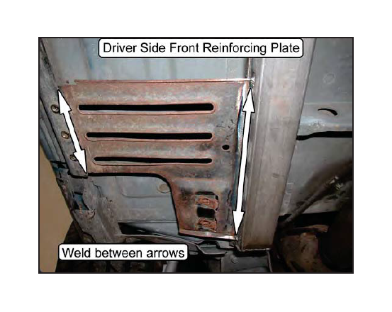
Using a Vice Grip or similar holding device, clamp the front factory reinforcing plates back into their stock locations. The cut-off portion of the front factory reinforcing plates should be touching the subframe connectors along the entire cut-off length.
NOTE: Make sure that the factory reinforcing plates are parallel to the ground when reinstalled. Ifthe plates are mis-positioned, and angled too far from their factory locations, there may be interference with the rearward portion ofthe factory convertible X-brace.
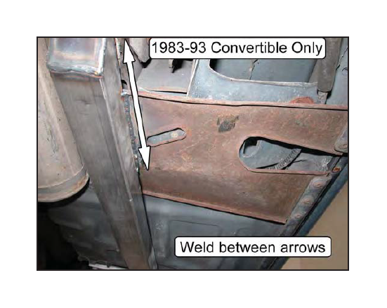
39. Weld the factory reinforcement plates to the subframe connectors and to the reinforcing Z-rail that is riveted to the rocker panel's lower pinch weld along the entire length indicated by the arrows below.
40. Clean the weld areas and paint with a high quality rust proof primer and topcoat.
41. Reinstall any bolts/rivets holding the fuel and brake lines in place.
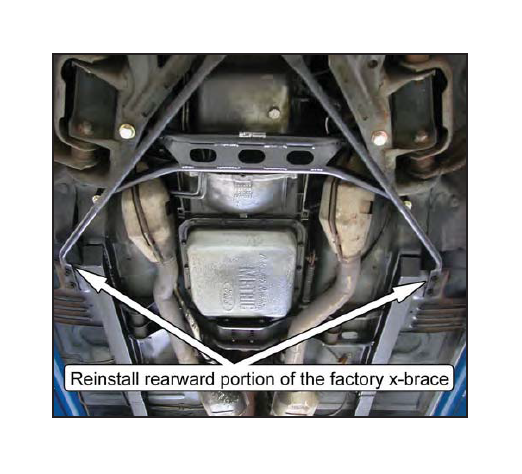
42. 1983-93 CONVERTIBLE ONLY, ALL OTHERS SKIP:
Reinstall the rearward portion of the factory X-brace and torque the mounting bolts to 32 Ib-ft.
43.) Test drive and enjoy!!!
