FREE 1 to 3-Day Delivery on Orders $119+ Details
Best Sellers


How to install a MSD Pro Billet Ready To Run Distributor on your 1979-1985 Mustang
Installation
Parts Included:
- 1 - Pro-Billet Distributor
- 1 - Rotor, PN 8467
- 1 - Distributor Cap, PN 8431
- 1 - Advance Kit
- 1 - O-ring Seal
- 1 - Vacuum Advance Lock-Out Kit
- 1 - Tube of Gear Lubricant
- 1 - Wiring Harness
- 1 - Gray Tach Jumper
Note: The terminals of the Ready-to-Run Ford Distributors require spark plug style terminals. You may need to change the terminals and boots of your wires. MSD offers two kits, PN 8849 or PN 8848 that are supplied with nine boots and terminals.
TIMING FUNCTIONS
Before continuing with the installation, here are a few definitions you should be aware of:
Initial Timing: This is the base timing (also referred to as idle timing) of the engine before the centrifugal advance begins.
Centrifugal Advance: The centrifugal (or mechanical) advance mechanism is made up of weights, springs, advance cams, and an advance stop bushing. The amount and rate of advance that your distributor is capable of is determined by the centrifugal timing. If you ever wish to lock out the centrifugal advance, refer to the centrifugal advance section.
Total Timing: This is the total of the initial timing plus the centrifugal advance added together. Example: 10° Initial 25° centrifugal = 35° Total Timing. (When checking Total timing, disconnect and cap the vacuum canister and plug the vacuum line.)
Vacuum Advance: The vacuum advance will advance the timing up to 10° during partial throttle driving (with 15 lbs of vacuum). The vacuum line should be routed to a ported vacuum outlet above the throttle plates.
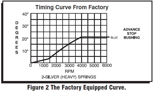
Note: MSD Distributors are supplied with the heavy (slow) advance springs and the 21° stop bushing installed. This is to prevent detonation in certain applications. Review the information on pages 2-3 to determine the best advance curve for your application.
RPM LIMIT AND TACHOMETER INFORMATION
Tach Signal: The Ready-to-Run Distributor features a Gray Tach Output wire which provides a clean signal for most tachometers and even some aftermarket fuel injection systems. The signal output is a 12 volt square wave, 20° duty cycle. This wire is also responsible for programming the built-in rev limiter.
Rev Limiter: The Ready-to-Run Distributor has a built-in rev limit that can easily be adjusted from 2,000 rpm to over 10,000 rpm. The default is 10,000 rpm. To set the rev limiter, run the engine to half the desired rpm then ground the Gray Tach wire (a jumper is supplied) for approximately one second. Every time the key is turned to the On position, the tach will display the programmed rpm limit. See page 8 for the programming procedure.
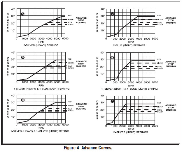
CHOOSING AN ADVANCE CURVE
The function of the advance curve is to match the ignition timing to the burning rate of the fuel and speed (rpm) of the engine. Any factor that changes the burning rate of the fuel or the engine speed can cause a need for an ignition timing change. Figure 1 shows some of the factors that will affect engine timing.
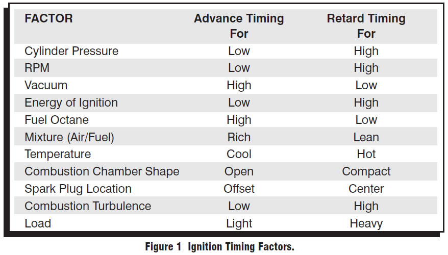
The timing mechanism of the distributor must make timing changes based on these factors.
Example: An engine has 11:1 compression, a high energy ignition and turns 5,500 rpm. With the specifications given, you will have to retard the timing for the high compression, low rpm and high energy ignition. By comparing the engine’s specifications against the chart, a usable timing guideline can be found. Engines with a combination of items from both columns will require a timing that is set in the mid range. Obviously a full technical explanation of correct ignition timing would be very complicated. The best way to arrive at a suitable ignition curve for your engine is to use the Ignition Timing Factors Chart as a guide and compare it to the Advance Graphs in Figure 4 until a suitable curve is found. When selecting your advance curve, use detonation (engine ping) as an indicator of too much advance, and a decrease in power as an indicator of too little advance.
TIPS ON SELECTING AN ADVANCE CURVE
- Use as much initial advance as possible without encountering excessive starter load.
- Start the centrifugal advance just above the idle rpm.
- The starting point of the centrifugal advance curve is controlled by the installed length and tension of the spring.
- How quickly the centrifugal advance (slope) comes in is controlled by the spring stiffness. The stiffer the spring, the slower the advance curve.
- The amount of advance is controlled by the advance bushing. The bigger the bushing, the smaller the amount of advance.
CENTRIFUGAL ADVANCE CURVE
SELECTING THE ADVANCE SPRINGS
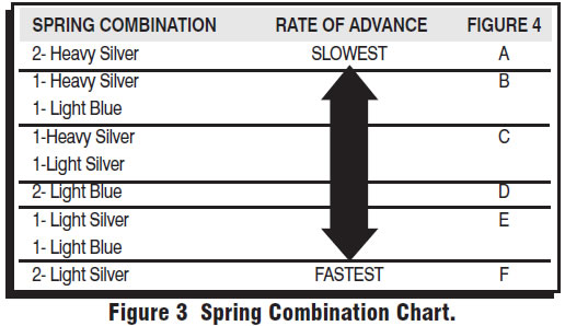
The rate, or how quick the advance comes in is determined by the type of springs which are installed on the distributor. The MSD distributors are equipped with two Heavy Silver springs installed. These will give you the slowest advance curve possible (Figure 2). The parts kit contains two additional sets of springs which can be used to match the advance curve to your particular application. Refer to the Spring Combination Chart (Figure 3) for combinations that can be achieved.
To change the springs, remove the cap and rotor and use needlenose pliers to remove the springs. Be sure the new springs seat in the groove on the pin.
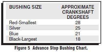
SELECTING THE ADVANCE STOP BUSHING
Three different advance stop bushings are supplied in the distributor kit. The distributor comes with a Blue (21°) bushing already installed. If a different amount of centrifugal advance is desired, follow the next procedure to change the bushings. The chart in Figure 5 gives the size and approximate degrees for the corresponding bushings.
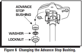
CHANGING THE ADVANCE STOP BUSHINGS
1. Remove the distributor cap and rotor.
2. Remove the locknut and washer on the bottom of the advance assembly (Figure 6).
3. Remove the bushing and install the new one. Install the washer and locknut.
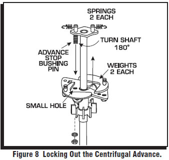
LOCKING OUT THE CENTRIFUGAL ADVANCE
1. Remove the cap and rotor.
2. Remove the advance springs, weights and the advance stop bushing from the advance assembly.
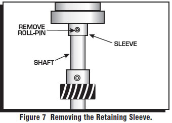
3. Remove the roll-pin from the shaft and slide the retaining sleeve down. It should not be necessary to remove the gear (Figure 7).
4. Slide the shaft two inches out of the housing.
5. Rotate the shaft 180° and insert the advance stop bushing pin into the small hole on the advance plate (Figure 8).
6. Install the locknut and washer to the advance stop bushing pin.
7. Install the retaining sleeve and roll-pin.
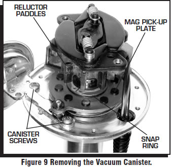
OPTIONAL VACUUM ADVANCE LOCKOUT
If you do not want to use the vacuum advance canister of the MSD Distributor, MSD has supplied the distributor with a lockout mechanism. The Lockout bolts in the position of the vacuum canister and will hold the pickup assembly firmly in place. The installation is easiest with the distributor out of the engine.
1. Remove the two Allen head screws that hold the advance canister (Figure 9).
2. Remove the snap ring that holds the magnetic pickup assembly in place. This is easy to do with a set of snap ring pliers by straddling one of the reluctor paddles.
3. Gently lift up on the mag pickup plate and slide the vacuum canister out.
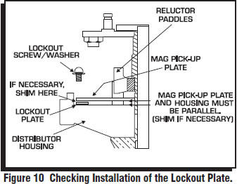
4. Install the Lockout Plate in place of the canister. Install the two retaining screws.
5. Install the supplied screw and washer through the Lockout and tighten. It is important to make sure the pickup plate is parallel with the housing of the distributor (Figure 10). If it is cocked or slanted, the paddles of the reluctor may contact the pickup. Check the clearance by rotating the distributor shaft. If necessary, use the supplied shims under the Lockout hold-down to correctly position the pickup plate.
Note: If no shims were required, use one beneath the washer of the Lock-Out Hold Down Screw.
6. After checking the reluctor to pickup clearance, tighten the Lockout retaining screws and install the snap ring.
7. Install the distributor, rotor and cap. Check the timing when complete.
Note: Do not forget to plug the original vacuum advance hose.
INSTALLING THE DISTRIBUTOR
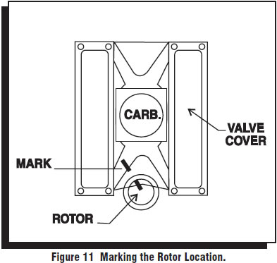
1. Remove the existing distributor cap without disconnecting any of the spark plug wires.
2. With the cap off, crank the engine until the rotor is aimed at a fixed point on the engine. Note this position by making a mark (Figure 11).
3. Place the distributor cap back on and note which plug wire the rotor is pointing to. MARK THE SPARK PLUG WIRES and remove the distributor cap.
4. Disconnect the wiring from the distributor.
5. Loosen the distributor hold-down clamp, slide the clamp out of the way and lift the distributor out of the engine.
6. Install the supplied O-ring seal in the groove on the distributor land. Apply a thin layer of oil to the housing O-ring.
7. Apply a liberal amount of the supplied break-in lubricant to the gear.
8. Install the distributor making sure that the rotor comes to rest pointing at the fixed mark. If the distributor will not fully seat with the rotor pointing to the marked position, you may need to rotate the oil pump shaft until the rotor lines up and the distributor fully seats.
9. Position and tighten the hold-down clamp onto the distributor.
10. Install the rotor and distributor cap. It is recommended to use a drop of Blue Loctite on the distributor cap hold down bolts.
11. Install the spark plug wires from the old cap one at a time to ensure correct location.
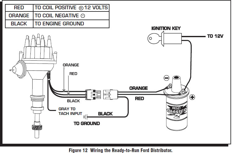
12. Connect the supplied wiring harness to the distributor. Route the wires to their connections as shown in Figure 12.
13. Page 8 shows how to set the rev limiter and connect the tachometer.
TACHOMETER INFORMATION
The MSD Ready-to-Run has a Gray wire that provides a 12 volt square wave, 20° duty cycle tachometer signal that will trigger most tachometers. It is recommended to connect this lead to your tach’s trigger input wire and check its operation. Note that the rpm limiter is extremely accurate and due to the variety of tachometers available, there may be differences in the displayed rpm.
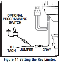
PROGRAMMING THE REV LIMIT
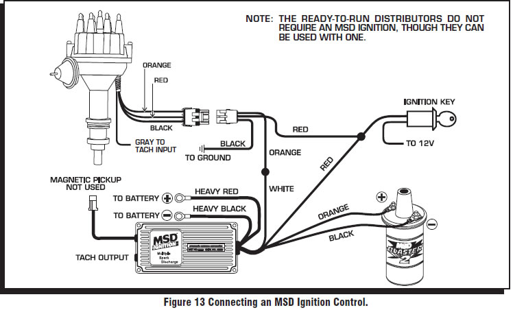
A tachometer is required to set the rev limit. The limit is programmed by running the engine at half the desired rpm, then momentarily grounding the Gray tach output wire from the MSD. A Gray jumper wire is supplied to connect to the tach with another tee-splice coming off to use for programming. A switch may also be installed to ease adjustments of the limiter (Figure 14). The default rpm limit is 10,000 rpm and the limit is adjustable from 2,000 - over 10,000 rpm..
1. Start the engine and bring the rpm to half the desired rev limit (for a 6,000 rpm limit, raise and hold the rpm to 3,000).
2. While holding the rpm steady, short the Gray tach wire to ground for approximately one second. Note that the tach will go to zero while grounded.
3. The tach will now display the programmed rev limit amount for two seconds. If this value does not register on the tach, repeat the procedure and try a different ground source.
4. To confirm the rev limit value, turn the ignition key to the On position (without cranking the engine). The rev limit value will be displayed for two seconds on the tachometer.
Note: This rpm confirmation only displays when the Gray wire is being used to trigger the tachometer.