FREE 1 to 3-Day Delivery on Orders $149+ Details
How to install an MSD Programmable Fuel Pump Voltage Booster on your Mustang

Shop Parts in this Guide
Installation
Parts Included:
- 1 - Programmable Fuel Booster, PN 2351
- 1 - Software CD
- 1 - Parts Bag
- 1 - Harness
- 1 - USB Cable
The Programmable Fuel Pump Booster will increase the voltage to the fuel pump in proportion to manifold boost pressure. The maximum voltage output is 22. The minimum output will be the battery voltage.
Note: It is recommended to have the Service Manual for your vehicle to identify the original wiring and fuel pump relay.
RATING: Continuous Power: 275 Watt, Peak Power: 375 Watt (one minute)
InSTALLATION
The MSD Fuel Pump Booster must be wired inline with the factory fuel pump relay. The factory has safety features built in, such as an inertia switch and high pressure shut-off which must be retained.
The MSD Fuel Pump Booster can be mounted in any position and is completely potted with a polyurethane compound for vibration resistance. Keep the unit away from direct engine heat sources and make sure all of the wiring reaches their connections. Also, allow access to the USB port.
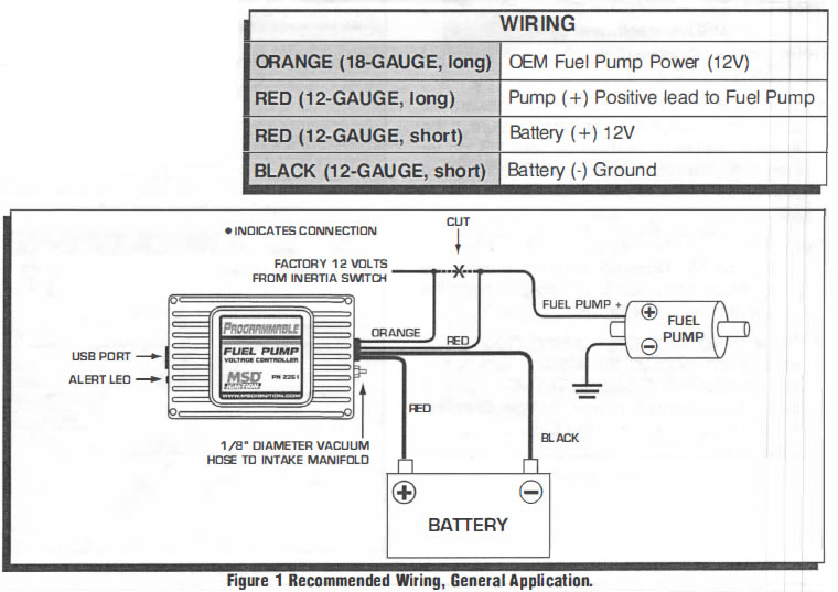
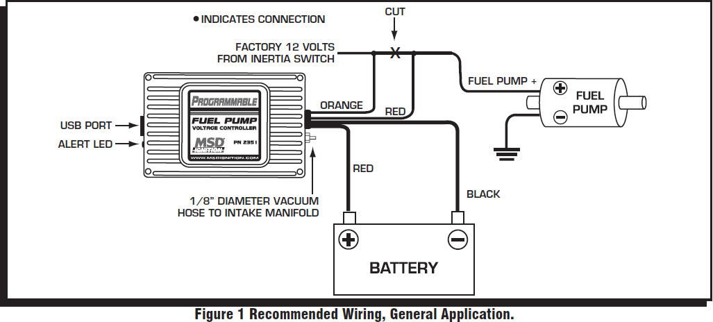
Use the unit as a template and mark the mounting holes. Remove the unit and drill the holes using a 3/16" bit. Mount the unit with the supplied screws. With the unit mounted, route the wiring to their connections. Also connect the boost pressure line to the booster and intake manifold (Figure 1).
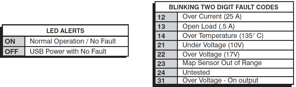
LED
The LED will blink fault codes to alert the following conditions. See charts.
MSDView SOFTWARE INSTALLATION
In order to install and run the MSDView software, the following minimum requirements are recommended:
- Microsoft Windows XP/Vista
- Keyboard and Mouse or some other compatible pointing device.
- Video adapter and monitor (800 X 600) or higher resolution.
- Available USB port.
- .NET 2.0 or higher.
- Internet access.
Important: Exit all programs before installing the MSDView software.
Note: Internet Access is required to install the MSD View software.
1. Insert the MSD CD into your PC. The software will automatically begin the installation feature. If the 'Autorun' feature is disabled on your PC, go to: Start and select Run, Select your CD Drive, and click on the Setup exe file. The MSDView wizard will walk you through the setup.
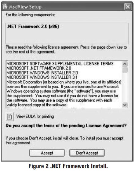
Note: If the .net framework is not installed on your PC, the MSDView software will prompt the download and setup. Click Accept to begin the udpate and follow the steps (Figure 2).
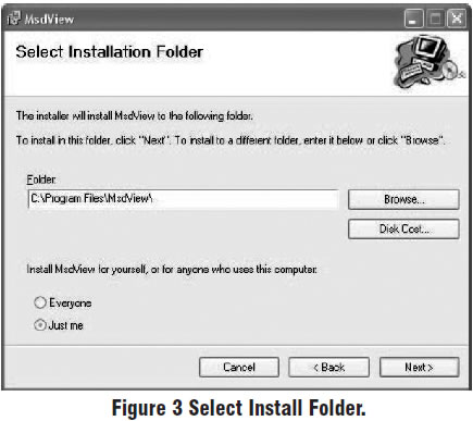
2. You will need to answer several questions such as a default location, the available disk space and permissions (Figure 3). The MSDView will also place a shortcut on your desktop. Once the installation is complete, select Close to finish the installation.
TUNING
It is recommended to have a fuel pressure gauge when testing and tuning with the Programmable Fuel Pump Booster. The fuel pressure should hold steady under full boost. Use your boost pressure as a starting reference point. Use the MSDView software to make the needed adjustments for optimum performance. The following pages explain how to load and use the MSD Software (Figure 4).
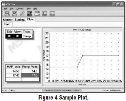
In the example in Figure 4, as the MAP reading increases from 14.5 p.s.i. the pump voltage will increase.
First Time Product Connection
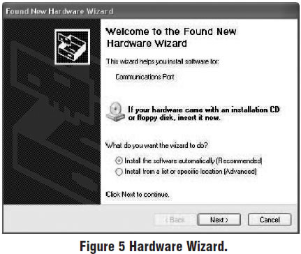
The first time the MSD is connected to your PC, a driver will need to be installed on your PC.
1. Connect the supplied USB harness to the PC and the MSD. The Found New Hardware Wizard window will open and walk you through the driver installation steps (Figure 5).
2. The Wizard will detect the Comm Port and install the required files. This may take a few moments.
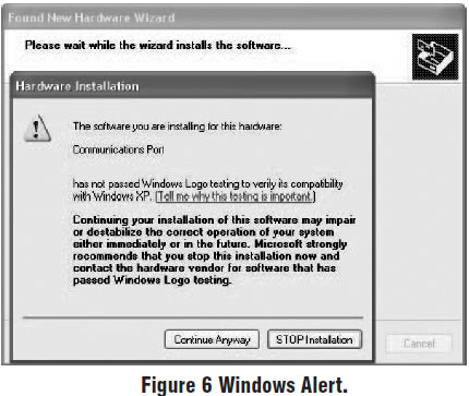
3. The Hardware installation window will stop the setup to alert you about the installation. Click Continue Anyway and then Finish to complete the installation (Figure 6).
Using the MSDView Software
With the MSD connected, open the software by clicking the icon on your desktop. The screen will prompt for the MSD product part number (PN 2351) to be selected.
The MSD software is a Graphical User Interface (GUI) design that incorporates the familiar Windows style operating environment. There are three tabs that you can select; Monitor, Settings and Plots.
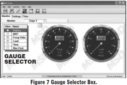
Monitor: The Monitor Tab allows you to view gauges for real time readings of the voltage and amps (Figure 7).
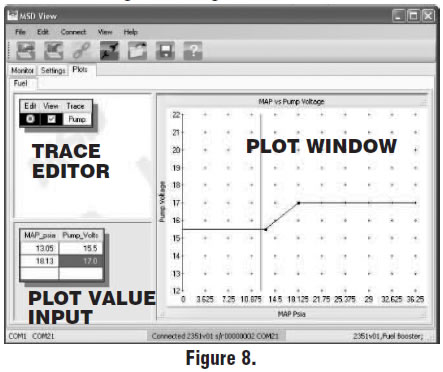
Plots: This tab will display the Trace editor, the Plot value input and widow (Figure 8).