 FREE 1 to 3-Day Delivery on Orders $149+ Details
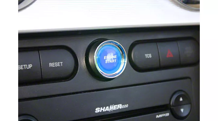
How to Install an SHR Illuminated Push Button Start Ignition Kit - Blue on Your 2005-2009 Mustang
Installation Time
2 hours
Tools Required
- Standard Pliers
- 7mm socket
- Wire Strippers
- 8mm Wrench
- T-20 Torx Bit
- Trim Removal Tool
- Ratchet / Nut Driver & extension
- Flat & Phillips screwdrivers
Shop Parts in this Guide
Installation
Thank you for your purchase of SilverHorse Racing products. Please read all directions before beginning the installation. A factory shop manual should be available for reference during instalation. If, after reading these and any acccompanying directions, you feel that you may not be able to complete the installation safely and properly, please seek out professional installation by certified technicians. Please read and understand our product purchase agreement (included on yellow sheet) prior to starting installation. Vehicle shouuld be off and in park with parking brake set prior to beginning installation. Each kit is electrically tested prior to leaving SHR to insure it illuminates and functions properly.
Directions:
1. Open hood and disconnect battery negative terminal with 8mm wrench and wait at least 5 minutes before proceeding. DO NOT have any auxiliary memory savers or power adders connected to vehicle that could inadvertently supply power to the RCM module.
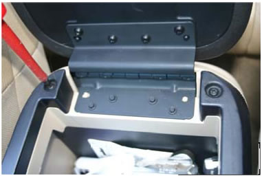
2. Remove the two Phillips screws inside the center console under the armrest (Fig.1)
3. Remove the center console upper half. If the car is an automatic, remove tee shifter bezel first by gently prying under the bezel. If the car is a manual, unthread the shifter knob, and remove the boot with the upper half of the console. To clear the upper half of the console, you will need to make sure the emergency brake is at the limit of its travel (full up) position. Additionally, if the car has ambient lighting, you will need to disconnect the wiring for the cup holder lights as well as the ambient light switch.
4. Remove both side covers from either side of the radio area of the dash, simply pull straight back away from the dash to unclip these. (Fig. 2)
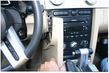
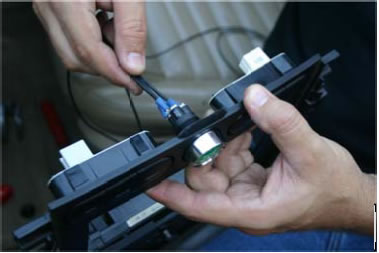
5. Remove the six 7mm screwws holding the radio plate in place. At the bottom of the trim plate on the passenger side is the wiring for the HHVAC controls. This connector’s locking “swing arm” must be released before it ccan be unplugged. It s grey and black in color, and must be accessed from behind the dash prior to full removal due to its short wire length. Release lock and disconnect. (Fig. 3) On the lower left driiver’s side of the radio plate, remove the fan wiring connector.
6. As you remove the trim plate, carefully disconnect the wiring at the top going to the buttons and existing power outlet. There are a total of three connectors across the top.
7. Lower Steering wheel to bottom of adjustment range.
8. Unclip instrument cluster dash cover and driver’s side air vent register. (Fig. 4)
9. Remove Driver’s side rocker cover. If equipped with entry lighting, disconnect during removal.
10. Using trim removal tool or equivalent, remove tree clip from driver’s kick panel. Unclip and remove driver’s kick panel.
11. R emove (2) 7mmm screws froom bottom o f driver’s side lower das h. Unclip remmaining clips and reemove. Discoonnect headli ght switch froom chassis wiring and leave atttached to lower knee area of dash.
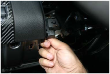
12. Using a T20 Torx™ bit (or Phillips screwdriver), remove the three screws on the bottom of the steering column. Unclip the upper and lower sections from one another, and remove steering column covers. (Fig. 5) – Note – some model years may have Phillips screws in these three positions – please verify which screw you have prior to removal.
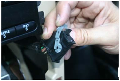
13. Disconnect ignition switch wiring connector found on left side of steering column, opposite ignition lock cylinder. Reach behind switch and feel for the connnector’s release clip to do this. (Fig. 6)
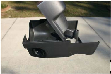
14. Place center radio cover plate face down on a towel, and release tthe clips holding aux. power outlet in place. The power outlet mounting ring may be damaged in this step, but it will not be re-installed. Remove power outlet plug. Screwdrivers or needle-nose pliers may help aid in removal.
15. Remove the included black plastic nut frrom the start button and route switch wiring through existing power outlet opening in Radio plate. From the backside, re-install nut onto switch, and align and tighten into place. (Fig. 7)
*** DECISION TIME ** Decide how you would like switch to illuminate (if at all) and follow the apppropriate wiring instruction (16, 17, or 18) for the ground wire below:
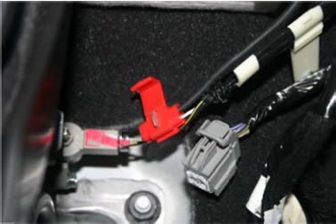
16. If you would like the start button to be illluminated when the key is in the ignition & the emergencyy brake is set, the ground (black) wire must be pulled from the switch harness split loom and safely routed separately with existing vehicle wiring to the emergency brake switch in the center console. Use supplied zip-ties as needed to safely rouute the wire and keep from any sharp edges. Wire will be connnected to parking brake switch pin 1 (red with yellow tracer)). This wire / connector can be found at the base of the parking brake, and you may have to unwrap some harness covering for access to the wire. (Fig. 8)
17. If you would like the start button to be illuminated ccontinuously when the key is in the ignition (constant on), the black ground wire will need to be connnected to vehicle ground just below instrument cluster near steering column. Keep wire in conduit and only pull it out far enough to reach the distance between the ground point and the steering column ignition switch in upcoming steps. This ground can be shared with any other common ground nearby on the metal portion of the dash.
18. If you do not want the switch to be illuminated at all (constant off), safely terminate the ground wire inside the conduit, and do not connect it to any vehicle ground.
Continue wiring:
19. Red and green wire in conduit (and black wire if following step 17 ) will need to be safely routed from center console to steering column by routing with existing factory wiring.
20. Once routed, using supplied tap connector, connect Red wire to White wire with light yellow tracer (Pin 2 off ignition switch).
21. Using supplied tap connect r, connect Green wire to green wire ( pin 7) of ignition switch. Important – if you would lke car to start ONLY with use of buttonn, cut wire as it exits pin 7,, allowing wire as it goes back into the harness to only be connected to green wire from new start button. If you would like it to be “dual purpose”” and be able to start either with the key (as original) or with the start button (preferred installation meethod), DO NOT cut the wire, just safely tap into it with supplied tap connector.
22. Once wiring is connected, reconnect ignition switch connector and safely route wiring away from any moving parts. Zip tie to existing factory wiring and/or brackets with supplied zip ties and trim as needed.
23. Zip tie original power outlet wiring safely out of the way, and reinstall radio plate in original position, reconnnect wiring, and install 7mm screws.
Testing: Foor the following steps, be sure vehicle is in park if an automatic, neutral if a manual, wheels are safely blocked, and emergency brake is set .
24. Reconnect battery negative ground cable.
25. Sitting in driver’s seat, place key in ignition. If illumination ground wire was connected to emergency brake wiring or directly to ground, start button should illuminate. If it is wired to do so and does not, re-check connections.
26. If switch is wired to turn off when emergency brake is released, test for proper operation by doing the following: hold foot firmly on brake pedal and release emergency brake. Illumination should turn off. Set emergeency brake and switch should re-illuminnate, along with parking brake warning light on instrument cluster.
27. Turn key to on position, but do not start. With transmission in neutral (manual) and clutch depressed, or in park (automatic) and foot on brake, press start button. Engine should start. If it does not, remove key and re-check connections. If engine does start, turn back off.
28. If blue-white wire on pin 7 of ignition switch connector was not cut in step 35, check for “normal” operation with ignition key by attempting to start with key only. Engine should start. Turn engine back off after testing .
29. If above tests are successful, remove key from ignition and complete re-assembly of remaining dash covers and center console cover by reversing steps 12 to 2.
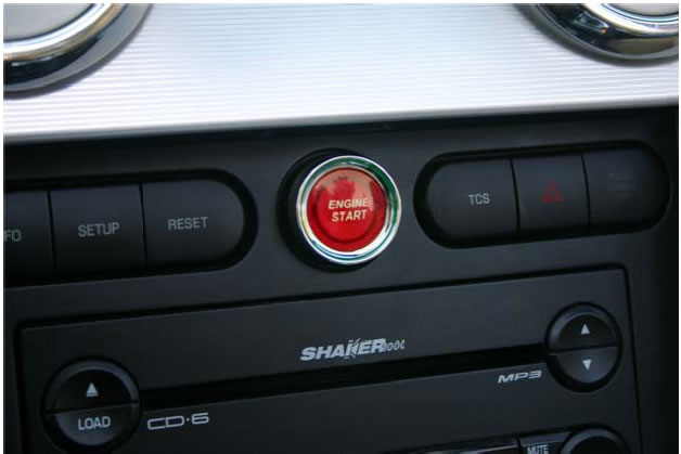
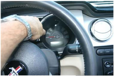
Completed Installation shown above.
Note: The lettering on the button itself is pad-printed (paint stamped). The use of gentle cotton towels moistened with a small amount of water are all that is required to clean the button, should it become necessary. The use of harsh cleaners or abrasive paper towels is not recommmend, and can damage the visual apppearance of the button as testing has shown. Care should be taken when using the start button to avoid pressing with long fingernails or jewelry, as this may scratch the face of the button.

