 FREE 1 to 3-Day Delivery on Orders $149+ Details
Simco 1996-1998 Mustang Gauge Cluster Installation Guide
Installation Time
1 hours
Tools Required
- Simco Graphic Appliqu and EL Lamp Assembly.
- Bezel Assembly.
- EL Inverter.
- Lamp Socket Connector Pigtail.
- (4) Pointer Stops (3 used in installation, 1 extra).
- (2) Long Pointers.
- (4) Short Pointers.
- Calibration Overlays w/ Instructions.
- 4 Strip of Tape.
- T-15 Torx Bit.
- Pointer Stop Insert Tool.
- Pointer Remover and Depth Tool.
- (2) Simco Stickers.
Installation
1. First disconnect the Negative (-) Battery Terminal and apply the Emergency Brake.
2. Remove the instrument cluster trim by the following steps.
3. Tilt the steering wheel down to its lowest position.
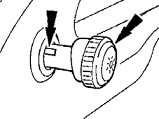
4. Remove the headlamp switch knob by inserting a narrow tool or standard screwdriver in the slot on the side of the headlamp. Slide the tool along the slot moving towards the front end of the knob and pull the knob away from the dash to release the knob from the shaft. (See Figure 1)
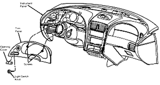
5. Remove the two black screws from the top-inside of the instrument panel trim with a T-15 Torx Bit or a 7mm Socket Driver depending on year of the vehicle. (See Figure 2).
6. Carefully pull instrument panel trim away from the dashboard by pulling directly outward on the panel. Carefully slide the panel out from behind the steering wheel and set aside.
7. Remove the original instrument cluster from the vehicle by the following steps:
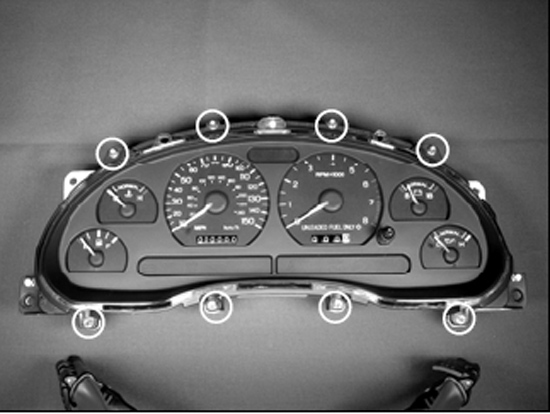
8. Remove the four screws in the top and bottom outer corners of the instrument cluster with a T-15 Torx Bit or a 7mm socket driver. (See Figure 3)
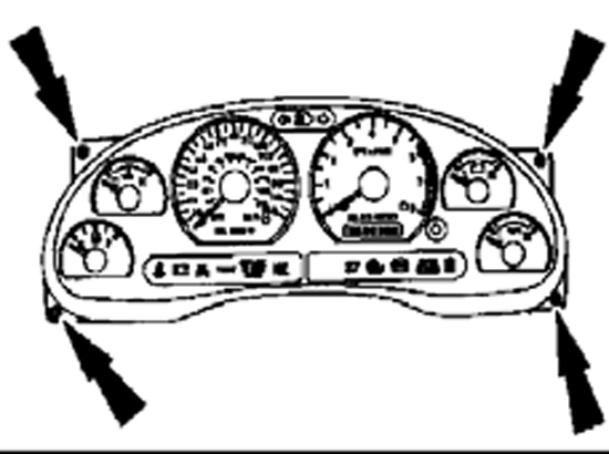
9. Carefully pull the cluster slightly forward and tilt it back and upwards allowing room to remove the two harness connectors. (See Figure 4)
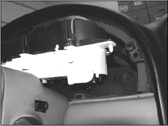
10. Disconnect the two harness connectors from the backside of the cluster. (See Figure 5)
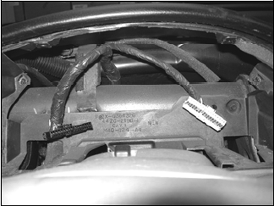
11. Remove the cluster from the vehicle.
12. Place the original cluster on a clean surface.
13. Remove the original bezel lens from the cluster and reinstall the cluster for calibration by the following steps: Important: When touching and rotating the pointers it is very important to use a soft touch and rotate in a slow and steady motion.
14. Remove the eight screws around the bezel lens with a T-15 Torx Bit and set the screws aside for later use. Remove the bezel lens from the cluster. (See Figure 6)
15. Locate the 3 pointer-stops that are pressed into the original appliqué surface. Remove them by pulling perpendicular from the original appliqué surface. Pointers may need to be gently rotated Clockwise (CW) away from the pointer stop. Pliers may be necessary. (See Figure 7)

16. Install the instrument cluster without the bezel lens into the instrument panel of the vehicle and reconnect the two harness connectors. Position the cluster in the instrument panel that will allow the most ease for marking the calibration points on the calibration overlay.
17. Obtain the cluster calibration data by the following steps: Important: Installation temperature conditions must be identical for the temperature gauge pointer to be accurately re-installed as well as RPM idle position.
18. Note: If pointer tips are gently rotated Clockwise (CW) with the ignition in the ON position, the pointers should return to their original position before rotation. Each pointer will take a different amount of time to return to its original position after gentle rotation. This is due that each gauge driving the pointer is dampened with a specific amount and type of fluid. For example, the Fuel gauge will take much longer to return back to its original position because it is heavily dampened with fluid. The dampening compensates for the sloshing of fuel in the fuel tank while the vehicle travels down the road. On the other hand, the Tachometer gauge is lightly dampened with fluid allowing the pointer to quickly rotate when the engine speed (RPM) changes.
19. Place the calibration overlay over the existing graphics and pointers, locating the overlay on the five pins of the white rear housing. (See Figure 8)
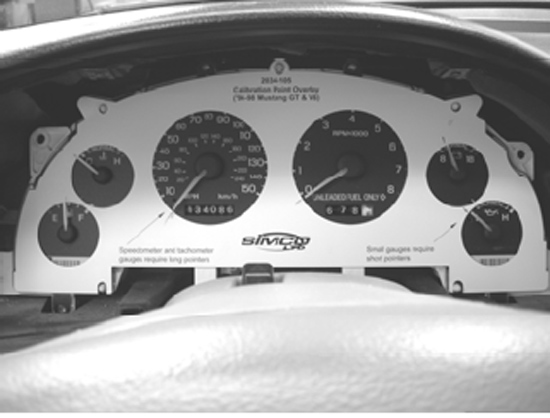
20. Reconnect the Negative (-) Battery Terminal.
21. Turn the ignition key to the ON position (position just before starting the engine). Holding the calibration overlay in place, use a pen or fine tipped marker to mark the locations of all six pointers directly onto the calibration overlay. The best way to do this is to start out with a cold vehicle (not running), start the engine, mark the points, then shut off the engine until it is time to reinstall the pointers. You can double check your marked calibration points by turning the vehicle off and restarting it to make sure that the marked locations have not changed. It is very important to obtain accurate readings from all six gauges.
22. Disconnect the Negative (-) Battery Terminal.
23. Remove the calibration overlay and pull the cluster out of the dash by detaching the two large connectors on the backside of the original OEM instrument cluster.
24. Place the original cluster on a clean surface.
25. Install the Simco Graphic Appliqué and EL Lamp Assembly by the following steps:
26. Important: It is crucial that all gauge center holes in the graphic appliqué align with the center of the gauge shafts on the cluster.
27. Note: Original pointers and pointer stops will not be reused. OEM appliqué is lightly welded to the surface below. A small flat tip screw driver or razor blade will break the weld. Depending on the strength of the weld, the appliqué may pull off by hand with minimal force.
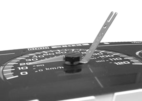
28. Using the pointer removal tool, remove the six pointers by gently prying upwards under the base of each pointer hub. (See Figure 9)
29. Test fit the Simco Graphic Appliqué and EL Lamp Assembly over the original graphics with the adhesive liner still intact to get a feel for placing the new graphics.
30. When you are comfortable placing the graphics, remove the original OEM graphic appliqués from the cluster.
31. Review the surface under the OEM appliqués and remove any dirt or debris that might affect the adhesion of the new appliqué.
32. Peel the liner attached to the back of the Simco Graphic Appliqué and EL Lamp Assembly and adhere the new graphic assembly to the flat cluster surface making sure to line up all gauge center holes with the gauge shafts.
33. Install the instrument cluster without the New Bezel Assembly into the instrument panel of the vehicle and reconnect the two harness connectors. Position the cluster in the instrument panel that will allow the most ease for staking the New Pointers at the marked calibration points on the calibration overlay.
34. Calibrate the instrument cluster with the New Simco Graphic Appliqué and EL Assembly by the following steps:
35. Place the calibration overlay over the New graphics, locating the overlay on the five pins of the white rear housing.
36. Remove the New Pointers from there packaging. The Long Pointers will be installed on the Speedometer and Tachometer locations and the Short Pointers will be installed on the Fuel, Water Temperature, Voltage, and Oil Pressure locations.
37. Place the new pointers onto the gauge shafts one-by-one by first aligning the pointer tip with the marked point on the calibration overlay and then lightly pressing the pointer onto the gauge shaft. Once the pointer is accurately aligned with the mark on the calibration overlay, firmly press the pointer onto the gauge shaft. Recommended staking pressure is about 8 lbs, but a firm push with your thumb will do. If the pointer needs to be adjusted, use the pointer removal tool to gently pry upwards on the hub of the pointer to release the pointer from the shaft and re-stake.
38. Once the instrument cluster has been calibrated, remove it from the vehicle and place it on a clean surface being careful not to touch or damage the new pointers.
39. Install the New Pointer Stops and Bezel Assembly by the following steps:
40. Note: Be careful not damage or abruptly touch new pointers.
41. Place each New Pointer Stop, located in the small pointer zip lock bag, in either end of the pointer stop installation tool (2” clear tube). The straight portion of the pointer stop should go into the tool.
42. Press the tapered end of the pointer stops into the holes in the following locations: speedometer, tachometer, and oil pressure. (See Figure 7 where the OEM pointer stops were removed)
43. Gently rotate the two long pointers counter clockwise (CCW) so they are just above the pointer stops.
44. Gently rotate the oil pressure, battery, and water temperature small pointers until they are in the Normal range. Gently rotate the fuel pointer until it is in between the Empty and Full range.
45. Place the New Bezel over the graphics locating the bezel on the five white pins in the white rear housing of the cluster.
46. Screw the bezel to the white rear housing using the eight brass screws removed in Step 5 with a T-15 Torx Bit. Figure 6 in Step 5 shows these screw locations.
47. Attach the Simco EL Inverter to the back of the instrument cluster by the following steps:
48. CAUTION: Be very careful to avoid bending of leads on EL Lamp. Damage may occur if proper care is not taken. Note: The lamp connector MUST have the red wire side facing down towards the bottom of the cluster. Note: New lamp connector is solely used as a power source; not intended to be filled with a lamp.
49. Remove the liner from the 4” strip of tape provided and strap the Simco EL Inverter to the flexible circuit. (See Figure 10)
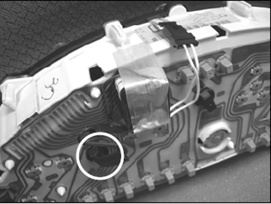
50. Connect the connector from the white leads to the connector on the Simco EL Lamp. (See Figure 10)
51. Remove the black lamp circled in Figure 10. This lamp is the second from the left if you are looking at the back of the cluster.
52. Plug the new lamp connector into the empty lamp socket so that the red wire is to the right, push downward and twist a quarter turn clockwise (CW) until the lamp connecter is firmly in place.(See Figure 10)
53. Finally, install the instrument cluster into the dash by connecting the two harness connectors to the rear of the instrument cluster and setting the unit into place. Re-install the four screws that attach the instrument cluster to the vehicle and re-install the instrument cluster trim removed in Step 2. Re-connect the Negative (-) Battery Terminal.
Installation instructions provided by Simco Ltd.
