 FREE 1 to 3-Day Delivery on Orders $119+ Details
Best Sellers


How to Install an SLP Line-lock Brake Control Line Lock Kit on your 2011-2012 Mustang
Installation
PACKING LIST
Before installation, use this check list to make sure all necessary parts have been included.
| ITEM | QTY | PART NUMBER | DESCRIPTION |
|---|---|---|---|
| 1. | 1 | 020402513 | Harness, Wire, Solenoid to Switch |
| 2. | 1 | 020402514 | Harness, Wire, Power to Switch |
| 3. | 1 | 020402515 | Harness, Wire, Solenoid to Ground |
| 4. | 1 | 260093711 | Line,Master Cylinder to Solenoid Brake, Camaro, 5th Gen |
| 5. | 1 | 260093712 | Line, ABS to Solenoid Brake, Camaro, 5th Gen |
| 6. | 1 | 020758100 | Solenoid |
| 7. | 2 | 020706250 | Self Drilling Hex Head Screws |
| 8. | 2 | 950330798 | Fitting, 1/2"x20 female SAE flare (45deg inverted double) to 1/8" NPT Male |
| 9. | 1 | 050501863 | SLP Logo Adhesive Label w/o dome resin |
| 10. | 1 | 020895524 | Switch |
| 11. | 1 | *** | Instructions |
WARNING: SLP Recommends wearing safety glasses for the complete installation.
WARNING: SLP Recommends allowing the vehicle to cool (not running) for five hours before beginning installation.
WARNING: Too avoid the chance of electrical shock or damage to your vehicle’s electrical system, disconnect both the negative and positive batter leads (in that order) at the battery.
INSTALLATION INSTRUCTIONS – #M25005
1. First drain the brake fluid from the master cylinder reservoir by either sucking the fluid out from the top or removing the rear brake line and letting the fluid drip into a cup. If the reservoir is not drained properly, brake fluid will drip onto you and the vehicles exhaust manifolds during the installation.
2. Next disconnect the negative battery terminal. Remove the factory airbox.
3. Next, remove the brake line that runs to the rear port of the master cylinder. To remove this line you must remove the nut that connects the line to the master cylinder and the nut that connects the line to the proportioning valve. See Figure 1 below for location of line in master cylinder.
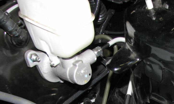
Figure 1: Rear port of master cylinder
4. Remove the nut from the proportioning valve on the opposite side of the line nut removed from the master cylinder. Remove this stock line from the vehicle. See photo 2 below for location in proportioning valve.
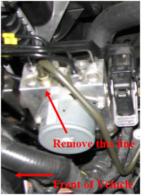
Figure 2: Removal of line in proportioning valve
5. On a work bench insert the included tube nut adapters (using Teflon tape on the 1/8” NPT side) into each end of SLP’s solenoid. Tighten the nut adapters.
6. Insert the master cylinder line into the vehicle by guiding the master cylinder end towards the brake booster. Route the master cylinder line underneath the master and into the rear brake fitting. Note this line will easily slide into place, if you experience difficulty you may be routing it through the wrong location. Additionally, this line will also snap into the factory line clip that the factory line was removed from. See Figure 3 for routing location.
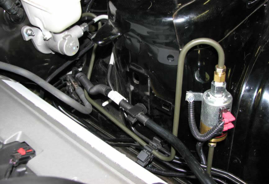
Figure 3: Master to solenoid routing path
7. Next loosely install the proportioning valve to solenoid brake line into the proportioning valve. See Figure 4.
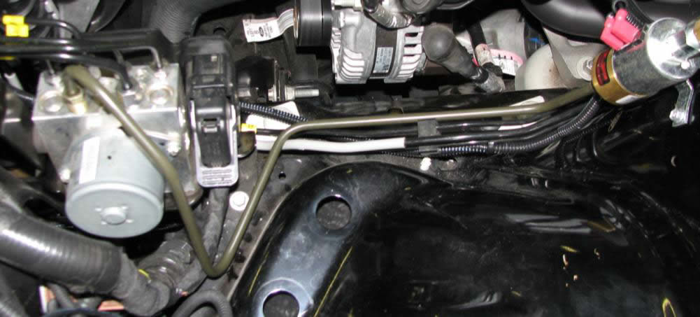
Figure 4: Proportioning valve to solenoid line routing
8. Next insert the solenoid between the two lines installed previously and loosely tighten (NOTE: Make sure the side marked MC is facing the Master Cylinder). Position the solenoid so that both lines are relaxed and mark through the mounting holes to the fender with a sharpie where you will be drilling for the mounting screws.
9. Remove the solenoid and drill a pilot hole on each mark made in step 8.
10. Reinstall the solenoid and FULLY tighten down all brake line fittings.
11. Mount the solenoid to the fender using the supplied hardware. At this time you can also install the short ground wire (with the ring terminal) under the head of one of the pilot screws. Install the spade connector as well. See Figure 5 below.
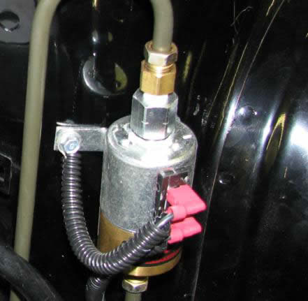
Figure 5: Installation of ground wire
12. Fill the reservoir with brake fluid.
13. BLEED THE BRAKE SYSTEM THOROUGHLY.
14. Next, install the other supplied wire harnesses. The harness with the add-a-circuit fuse is to be routed from the fuse box, across the firewall of the vehicle, through the grommet on the driver’s side into the cabin (grommet is under the brake booster), and then to your center console (or wherever else you wish). Zip-tie where appropriate. Pull out the 3rd 10A fuse and insert it into the lower of the two fuse slots on the add-a-circuit. There should already be a 10A fuse in the top slot, and you will add the fuse that you just pulled out. See Figures 6 and 7 below. Note the wire routing out of the fuse box.

Figure 6: Add-a-circuit fuse location and harness routing
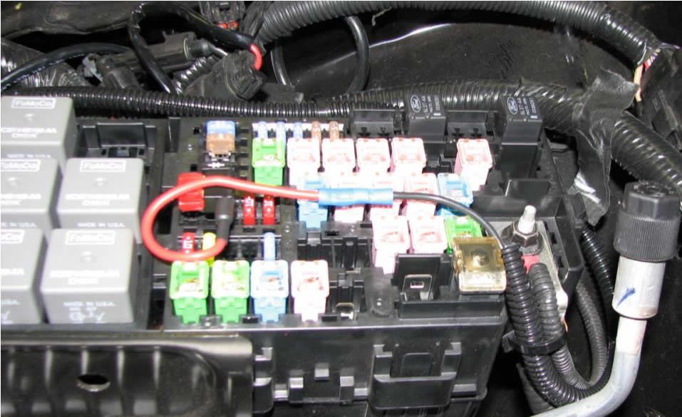
Figure 7: Add-a-circuit fuse location and harness routing
15. Mount the supplied switch anywhere from the kick panel to the center console. A ½” hole will need to be made so that the switch can be mounted. Once mounted, route the supplied 9’ wire with 2 female spade connectors through the fire wall (where the wire from the fuse box came from) and to the solenoid. Connect at the free spade terminal on the solenoid. Connect the two wire harnesses at the switch. A sample location is shown below in Figure 8.
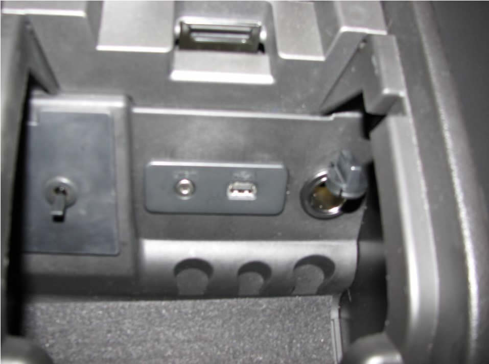
Figure 8: Sample location of switch location
16. Reinstall the airbox and start the vehicle. Re-bleed the brake system if necessary.
17. The installation is now complete.
