 FREE 1 to 3-Day Delivery on Orders $149+ Details
Mustang Speed Calibrator Installation Guide
Installation Time
60 minutes
Tools Required
- 2mm flat-blade screwdriver
- #2 Phillips screwdriver
- Dielectric grease
- Rags
- inch open wrench
- 8mm and 13mm sockets/ratchet
- Utility knife
- Adhesive velcro strips
- Multimeter
- Silicone RTV
- Floorjack and two jackstands
- 6 Zip ties
Installation
Refer to the photo above for terminology of included parts.
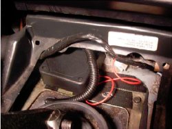
1. Determine what your stock gear ratio was before you installed the new gear set. You should be able to do this by looking at the tag on the differential cover at the back of the car. The tag should say something like 2L88, which means it’s a 2.88 ratio
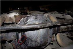
Rear axle with tag boxed in red.
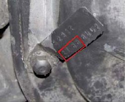
Tag numbers used to determine gear ratio.
2. Open the SpeedCal control box by unscrewing the four screws with the Phillips screwdriver and set the lower set of dip switches (the black set) based on the chart at this link: DIP Switch settings WARNING: DO NOT CHANGE THE RED DIPSWITCH BANK
After the dipswitch bank is set, close the SpeedCal back up with the four screws.
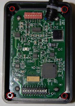
Opened SpeedCal with screw holes circled in red.
3. Remove the negative (black) battery cable from your car’s battery using the ½ inch wrench.
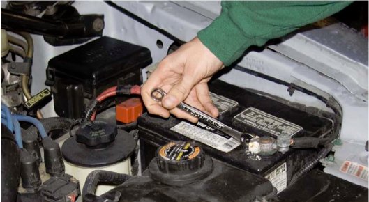
Removal of the negative battery terminal cable.
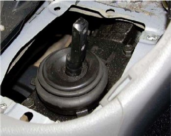
4. Remove the shift knob by unscrewing it counterclockwise, then lift off the outer boot. Be sure to disconnect the cigarette lighter power connector and, if applicable, traction control connector.
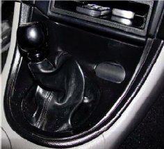
Shifter assembly fully assembled
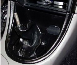
Shift knob removed
Outer shift boot removed
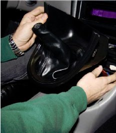
Outer shift boot removal
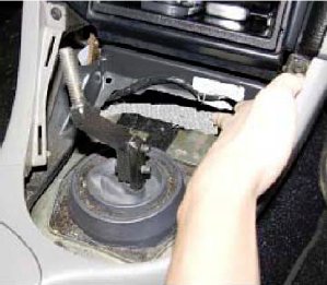
5. Remove the upper shifter arm by unscrewing the two bolts that hold it on using the 13mm socket. Then, remove the metal inner boot housing by unscrewing the four bolts holding it down using the 8mm socket. It should look like the picture below once you complete this step.
6. Cut a square approximately ½ inch per side in the inner shift boot at its driver’s side front corner with the utility knife. Only cut three of the four sides so it forms a flap. Then, feed the SpeedCal wiring harness through the hole and down the driver’s side of the transmission. Once this is completed, stick one side of the Velcro strips onto the metal inner boot housing as shown below.
7. Replace the inner boot and secure with the four 8mm screws.
8. Determine which of the two wires for the cigarette lighter is positive by using the multimeter in ohms mode. The wire that has extremely high resistance between it and the chassis of the car is the positive one. The ground wire should have almost no resistance between it and the chassis and should therefore read near zero ohms on the multimeter. Once the positive wire has been determined, connect the red wire of the SpeedCal to it using the scotch lock.
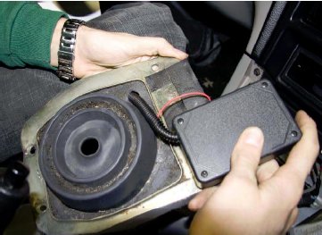
9. Stick the Velcro that will mate with the Velcro in step 6 on the bottom of the SpeedCal and attach the SpeedCal to the inner boot housing using the Velcro.
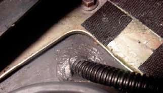
10. Use the Silicone RTV to seal up the hole caused by the cut in the inner boot as shown below.
11. Jack up the car in the front with the floorjack and secure it with the two jackstands.
12. Disconnect the VSS (vehicle speed sensor) connector from the transmission under the car.

Photo taken from behind the second driver’s side catalytic exhaust system. The VSS connector is circled in red.
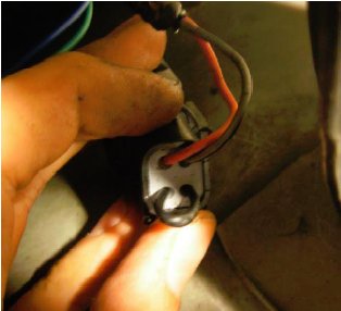
13. Pull out the red contact lock from the VSS connector shell using the flat-blade screwdriver. This is the connector that is attached to the wiring harness of the car, NOT the VSS itself.
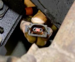
VSS connector
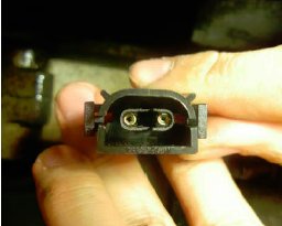
VSS connector with contact lock removed
14. Slide the flat-blade screwdriver GENTLY down the side of each electrical contact in the VSS connector shell and pull the contacts out of the connector shell from the other side.
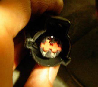
15. Push the blue and green SpeedCal harness wires into the back of the old VSS connector that was just removed. There should be a faint clicking noise when they are in all the way and you shouldn’t be able to pull them out with a gentle tug. It doesn’t matter which wire goes where. Then, apply some dielectric grease to the two contacts. Finally, put the red contact lock that was removed in step 13 back into place between the contacts.
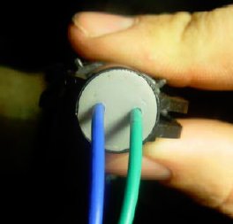
Rear of VSS connector with SpeedCal wires installed
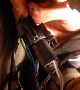
16. Reconnect the old vehicle harness connector assembled in step 15 to the mating VSS connector on the Transmission.
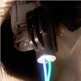
VSS connector attached to transmission
17. Push the two VSS vehicle harness wires into the back of the supplied connector shell as shown below. Note that for ’99-’04 Mustangs the pink/orange wire is gray/red. Make sure that the wires are oriented exactly as in the picture below, otherwise the SpeedCal will not function and the speedometer will always read zero. There should be a faint clicking noise when they are in all the way. Then, apply some dielectric grease to the contacts. Finally, push the supplied large red contact lock into place between the contacts.
Rear of connector shell with VSS vehicle harness wires installed.
Front of connector shell with large red contact lock installed.
18. Connect the SpeedCal harness to its mating connector, which was assembled in step 17. Double check to make sure that the colored (non-black) wire from the car (either pink/orange or gray/red, depending on the year of the vehicle) will mate to the Gray SpeedCal wire as polarity is very important and the SpeedCal will not function if the wires are crossed.
19. Secure all slack wires with zip-ties, making sure they are away from all exhaust components.
20. Reconnect the negative battery cable to the battery post with the ½ inch wrench. The SpeedCal should now be functional. Note that the small contact lock was never used.
Installation instructions provided by AmericanMuscle customer Jeff Braun
