 FREE 1 to 3-Day Delivery on Orders $149+ Details
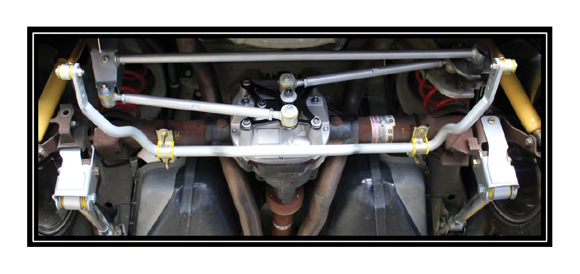
How to Install a Whiteline Complete Watts Link Rear Suspension on your 2005 to 2013 Mustang Coupe
Installation Time
4 hours
Tools Required
- Saftey Glasses
- Vehicle Lift / Jack & Jack Stands
- Metric Socket and Wrench Set (8,13, 15, 17, 19, 22, 24mm)
- 10mm Hex Drive Socket
- 1/4” Hex Drive Socket
- Torque Wrench
- 1+1/8” Wrench
- Blue Thread Lock
- Dow Corning RTV#732 (Or other equivalent gasket maker)
- Cable Tie
- Gear Lube and Friction Modifier
- Drain Pan
- Fluid Pump
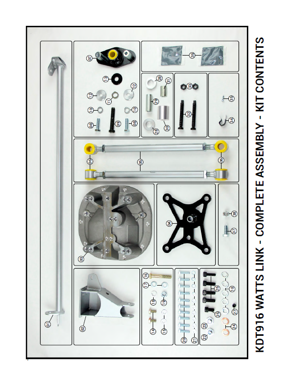
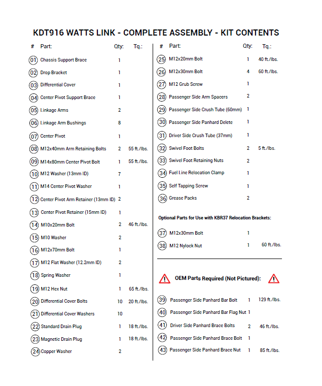
Please read all instructions carefully prior to installation and verify all kit contents and tools are on hand prior to installation.
Professional Installation by a Whiteline Performance Center is recommended.
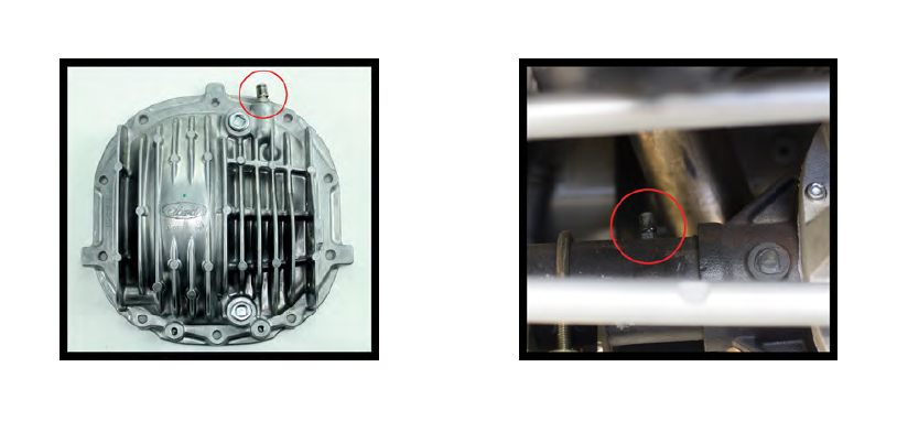
2013 and certain specialty Mustang models (BOSS 302) come equipped with the axle vent on located on the differential cover. With the installation of the KDT916, this vent will have relocated to the axle shaft. For more details, please contact Whiteline Support.
Instructions:
1. Lift and support the vehicle from the chassis.
2. Remove the Rear Sway Bar.
2.1. Disconnect the rear sway bar from the axle using a 15mm socket (Figure 01) and remove the factory links with the sway bar (Figure 02).
3. Remove the Panhard Rod and Brace
3.1. Remove the Panhard rod cover from the driver side mount to access the bolts.
3.2. Remove the 18mm nut and bolt Panhard bolt from the driver side and discard.
3.3. Using an 18mm wrench remove the (39) Passenger Side Panhard Bar Bolt and (40) Flag Nut. Save both of these for use later. (Figure 03)
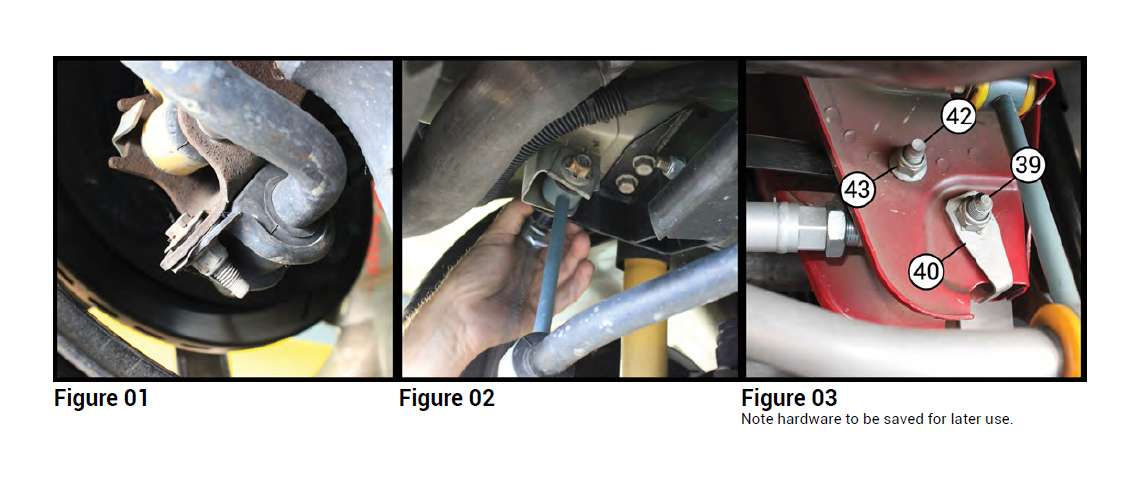
3.4. Remove the (42) Passenger Side Panhard Brace Bolt and (43) Nut. Save these for use later.
3.5. Remove the Panhard Rod.
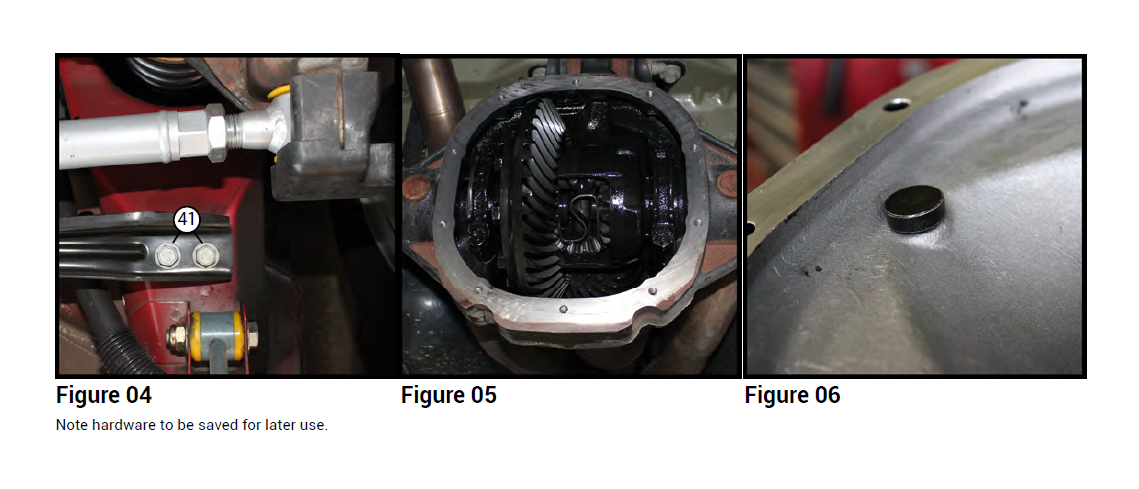
3.6. Remove the (40) Driver Side Panhard Brace Bolts and save these for use later. (Figure 04)
3.7. Remove the Panhard brace.
4. Replace Differential Cover
4.1. Place a drain pan underneath the differential. Loosen the factory differential cover bolts using a ¼” wrench and pry the cover loose to drain the fluid out of the differential.
4.2. Once the differential is sufficiently drained, remove the cover and thoroughly clean the mating surface. (Figure 05)
4.3. Thoroughly clean the inside of the new differential cover with a lint-free cloth.
4.4. Apply a small amount of Dow Corning RTV #732 to the threads of the (32) Swivel Foot Bolts and install them into the (03) Differential Cover by hand until they are flush. (Figure 06)
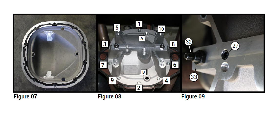
4.5. Apply a continuous bead of Dow Corning RTV #732 (or an equivalent gasket maker) on the mating surface of the differential cover. (Figure 07)
4.6. Using a 1/4” Hex Drive Socket, (20) Differential Cover Bolts and (21) Differential Cover Washers, install the (03) Differential Cover onto the car. Tighten the (20) Differential Cover Bolts following the numerical order indicated in (Figure 08).
4.6.1. Torque Specs:
4.6.1.1. (20) Differential Cover Bolts – 20 ft./lbs.
4.7. Tighten down the (32) Swivel Foot Bolts to 5 ft./lbs. using an 8mm socket and torque wrench. Then install the (33) Swivel Foot Retaining Nuts on to them to lock them in place. (Figure 09)
4.8. Apply a small amount of RTV to the (27) M12 Grub Screw and install it flush into upper left center hole bolt. (Figure 09)
Instructions:
5. Install Center Pivot and Drop Bracket
5.1. Thoroughly grease the interior of the (07) Center Pivot and install it on to the (04) Center Pivot Support.
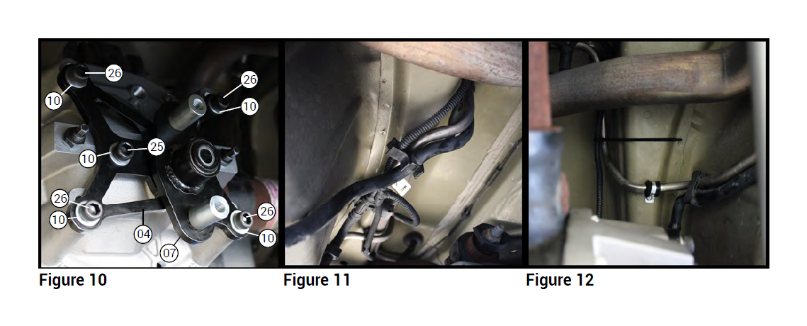
5.2. Install the (07) Center Pivot and (04) Support onto the (03) Differential Cover using the four (26) M12x30mm
Bolts, the (25) M12x20mm Bolt, and five (10) M12 Washers as shown in (Figure 10).
5.2.1. Torque Specs:
5.2.1.1. (26) M12x30mm Bolts - 60 ft./lbs.
5.2.1.2. (25) M12x20mm Bolt - 40 ft./lbs.
5.3. Rotate the plastic clip holding the 3 fuel system lines above the differential area. (Figure 11)
5.4. Remove the secondary clip from the side.
5.5. Using the (34) Fuel Line Relocation Clamp and the (35) Self Tapping Screw secure hard fuel line to the chassis, replacing the secondary clip. (Figure 12)
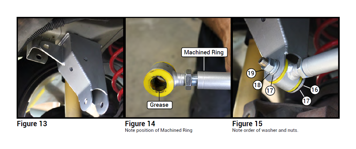
5.6. Apply a small amount of Blue Thread Lock to the two (41) Driver Side Panhard Brace Bolts and use them to install the (02) Drop Bracket to the chassis.
6. Install Linkage Arms
6.1. Install the (06) Linkage Bushings into the (05) Linkage Arms. Then thoroughly grease the interior of the bushings.
6.2. Note: One side of the (05) Linkage Arms has a ring machined into it. The ends of the arm with this ring both face the driver’s side during installation. (Figure 14)
6.3. Take one (05) Linkage Arm and install (31) Drive Side Crush Tube into the bushings on the side with the machined ring.
6.4. Then take side of the Linkage Arm without the machined ring and install it onto the lower pivot of the (07) Center Pivot.
6.5. Install the driver side of the Linkage Arm into the Drop Bracket using the (16) M12x70mm Bolt, two (17) M12
Flat Washers, the (18) Spring Washer, and (19) M12 Hex Nut as illustrated in (Figure 15).
6.5.1. Torque Spec:
6.5.1.1. (19) M12 Hex Nut- 65 ft./lbs.
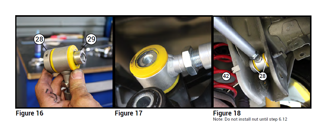
6.6. Take the remaining (05) Linkage Arm and install (31) Passenger Side Crush Tube into the end of the Linkage Arm without the machined ring. Install a (28) Passenger Side Arm Spacer onto each protruding side of the Crush Tube. (Figure 16)
6.7. Install the end of the Linkage Arm with the machined ring onto the upper pivot of the (07) Center Pivot. (Figure 17)
6.8. Then install the passenger side of the Linkage Arm to the chassis where the factory Panhard Brace was installed. Use the (42) Passenger Side Panhard Brace Bolt to hold the linkage arm in the chassis mount as illustrated in (Figure 18), but do NOT install the nut until step 6.12
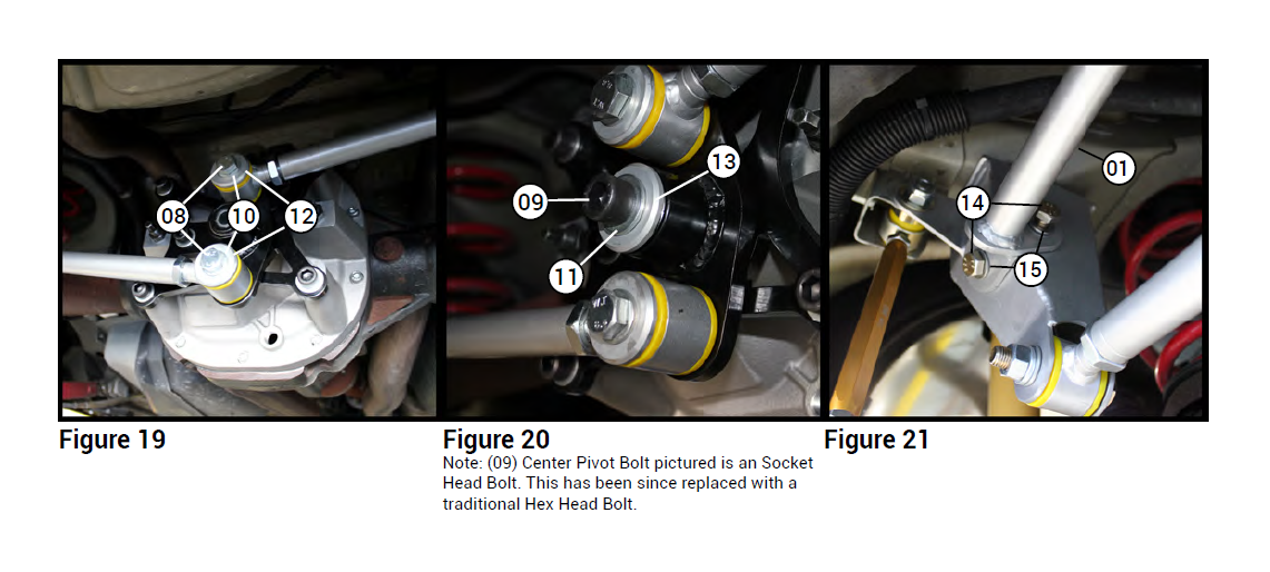
6.9. Apply Blue Thread Lock to the (08) M12x40mm Arm Retaining Bolts. Use a bolt with a (10) M12 Washer and a (12) Center Pivot Arm Retainer to secure each arm to the (07) Center Pivot. (Figure 19)
6.10. Secure the Center Pivot to the Diff Cover using the (09) M14x80mm Center Pivot Bolt with the (11) M14
Center Pivot Washer and (13) Center Pivot Retainer. (Figure 20)
6.10.1. Torque Spec:
6.10.1.1. (08) M12x40mm Arm Retaining Bolts - 55 ft./lbs.
6.10.1.2. (09) M14x80mm Center Pivot Bolt - 55 ft./lbs.
6.11. Apply Blue Thread Lock to the two (14) M10x20mm Bolts and use them to install the (01) Chassis Support
Brace onto the (02) Drop Bracket with the two (15) M10 Washers. (Figure 21), but do not tighten until the end of step 6.12.
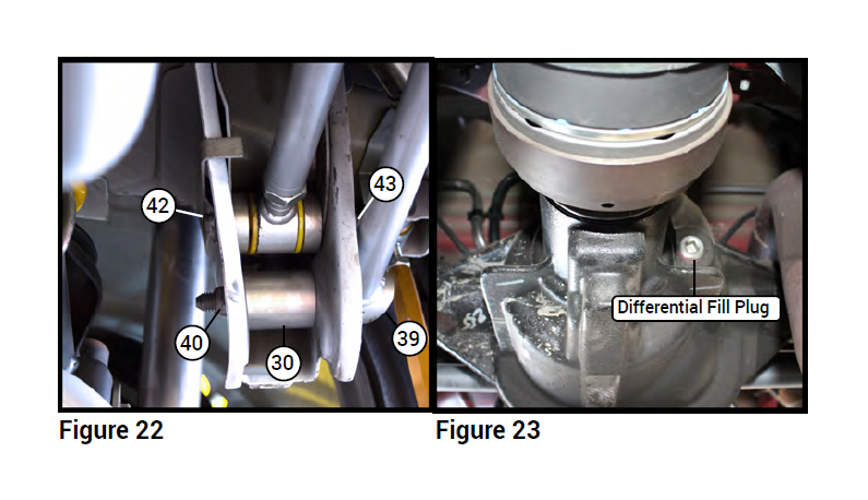
6.12. Install the passenger side of the (01) Chassis Support Brace on to the chassis using the (39) Passenger Side Panhard Bar Bolt, the (30) Passenger Side Panhard Delete, (40) Passenger Side Panhard Bar Flag Nut, and (43) Passenger Side Panhard Brace Nut as illustrated in (Figure 22). Torque the (01) Chassis Support Brace and Linkage Arm to the specs below.
6.12.1. Torque Specs:
6.12.1.1. (43) Passenger Side Panhard Brace Nut - 85 ft./lbs. (Figure 22)
6.12.1.2. (39) Passenger Side Panhard Bar Bolt – 129 ft./lbs. (Figure 22)
6.12.1.3. (14) M10x20mm Bolts - 46 ft./lbs. (Figure 21)
7. Fill Differential Housing With Fluid
7.1. Using a (24) Copper Washer install the (22) Standard Drain Plug into the oil feed hole [A]. Then use the remaining
(24) Copper Washer and install the (23) Magnetic Drain Plug into the drain hole [B]. (Figure 08)
7.1.1. Torque Specs:
7.1.1.1. (22) Standard Drain Plug – 18 ft./lbs.
7.1.1.2. (23) Magnetic Drain Plug – 18 ft./ lbs.
7.2. Remove the factory differential fill plug from the FRONT of the differential housing using a 3/8” ratchet driver/ extension. (Figure 23)
7.3. Fill the differential housing using the appropriate fluid specified by your differential manufacture.
7.4. Reinstall the differential filler plug and torque to 22 ft./lbs..
8. Reinstall Rear Sway Bar in reverse of removal.
8.1. Torque Spec:
8.1.1. Sway Bar Mount – 52 ft./lbs.
8.1.2. Sway Bar Link – 85 ft./lbs.
9. (Optional)
9.1. If the vehicle is equipped with KBR37 Control Arm Relocation Brackets, use the supplied (37) M12x30mm Bolt and (38) M12 Nylock Nut to replace the driver side Panhard Bar Bolt.
9.1.1. Torque Spec:
9.1.1.1. (38) M12 Nylock Nut – 60 ft./lbs.
10. Adjust the Axle Center
10.1. Cycle the vehicle suspension to make sure it is settled.
10.2. Determine the axle and differential position relative to the vehicle by measuring the distance between the wheels and chassis on each side.
10.3. Adjust the length of the Linkage Arms until the distance between the wheels and chassis are equal on both sides..
10.3.1. Example: To shift the axle to the passenger side, shorten the passenger side Linkage Arm and lengthen the driver side Linkage Arm.
10.4. Adjust the length of both Linkage Arms equally to rotate the Center Pivot until it is vertical or clocked just slightly counter-clockwise. The actual angle will vary depending on the vehicle’s ride height and range of suspension travel.
10.4.1. Note: Extending both arms will rotate the Center Pivot counter-clockwise and shortening both arms will rotate the Center Pivot clockwise.
10.5. Apply Blue Thread Lock and tighten down the jam nuts on the Linkage Arms with a 1 1/8” wrench.
11. Recheck all hardware after initial 100 miles.
Warning: Drive carefully while you accustom yourself to the changed vehicle behavior.

