FREE 1 to 3-Day Delivery on Orders $149+ Details
2005-2009 V6 Mustang CDC Shaker Scoop Installation Guide
Installation Time
3 hours
Tools Required
- Template
- Masking Tape
- Center Punch
- 1/8 Pilot Drill Bit
- 1 Hole Saw
- Drill Motor
- Saw with metal blade (for cutting hood)
- Utility Knife (for cutting hood blanket)
- Razor Blade
- Eye Protection
- Rivet Gun
- 80 120 grit sand paperTools List for Shaker Assembly and Install:15mm Socket 3/8" Drive
- 10mm Socket 1/4" Drive
- 8mm Socket 1/4" Drive
- 7mm Socket 1/4" Drive
- 7/16 Socket 1/4" Drive
- 1/4" Drive 6 extension
- 1/4" Drive Ratchet
- 3/8" Drive Ratchet
- 5/32 Allen Wrench
- Drill Motor
- 1/8" Pilot Drill
- 2 3/4" Hole Saw
- Rivet Gun
- Half Round File
- Threadlocker
- Utility Knife or Hobby Knife
- Eye Protection
- Drop Cloth
Shop Parts in this Guide
Installing the Trim:
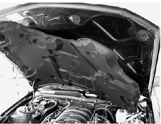
1. Raise Hood and remove under hood blanket. Use a fork tool to remove pushpin fasteners. Set hood blanket aside. Close hood and mask off entire area where Shaker opening will be cut out to help prevent paint damage during the cutting process. NOTE: Hood blanket may have different length pushpins so note where they are located upon removal.
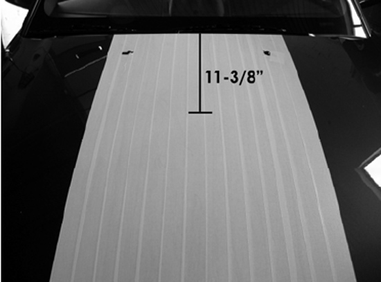
2. Measure and mark centerline on the hood. Measure and mark 11-3/8” from rear of the hood on the centerline. This will line up with the rear line on the shaker cutout template.
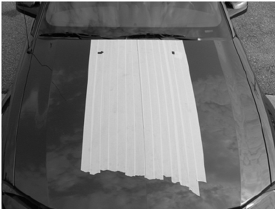
3. Align template with rear of hood and centerline as noted on template. Tape template securely to top of hood.
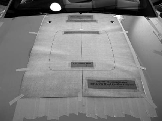
4. It is very important that the centerline of hood is measured accurately. Make sure to line up centerline of template to centerline on hood. The best way to achieve this is to cut out two triangles along the centerline. One at the rear of the template and one at the rear of the shaker hole outline. (As Shown Below)

5. With a sharp razor blade or X-Acto knife, cut through template, through the tape, and into the paint of your hood. Cutting/scoring the paint on the hood will reduce the chance of paint flake during the cutting process.
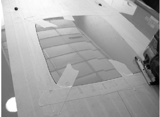
6. Remove template from hood and discard. Peel tape from center of Shaker opening, leaving an outline of Shaker opening. CAUTION: Add a second layer of masking tape around opening to reduce the risk of shavings scratching the hood.
7. During the drilling and cutting process, elevate the hood far enough to ensure no damage will occur to engine components. Place a blanket over engine to catch metal shavings.
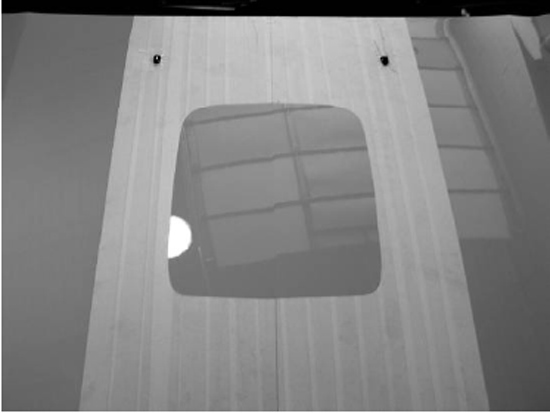
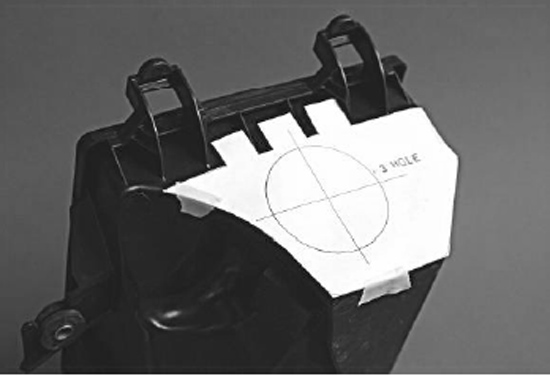
8. Center punch and drill a starter hole for Shaker opening with a 1” hole saw. Cut Shaker opening, following the outline of the tape. Stop cutting half way around opening and place masking tape over cut line for support; this will help prevent some vibration.
Installing Shaker
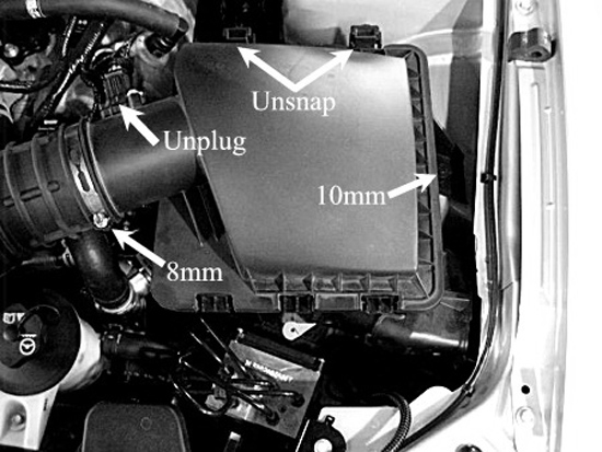
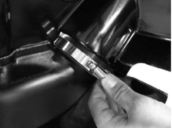
1. Remove Air Box by loosening hose clamp with 8mm socket and remove the 10mm bolt attaching the filter housing to the body. Unplug Mass Airflow Sensor at this time. Remove entire filter housing from vehicle.
2. Remove the 7mm coil pack bolts (4) and unclip the two wire looms to remove coil pack from mounting bracket.
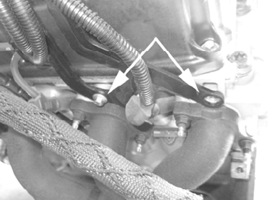
3. Remove the 8mm Bolts (2) from the top of the coil pack bracket.
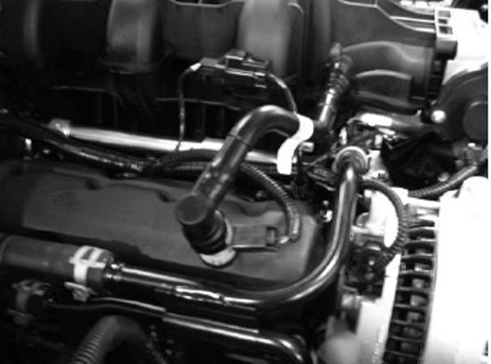
4. Temporarily remove the EVAC hose from the valve cover and the intake tube.
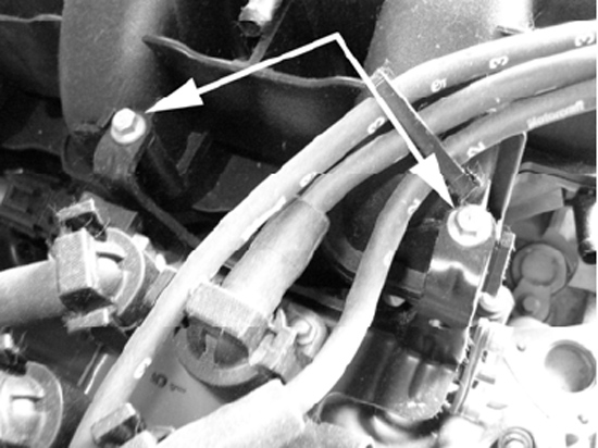
5. Remove the 10mm and 15mm bolts that secure the coil pack bracket to the side of the engine.
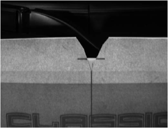
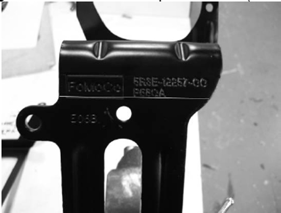
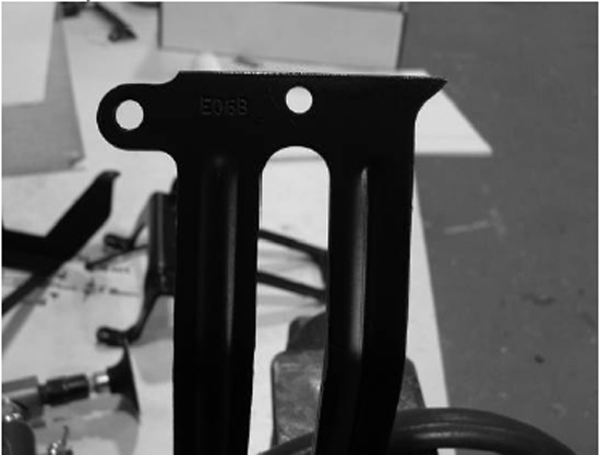
6. Trim the factory bracket with a cut-off wheel or hack saw. Follow lower horizontal line of the “FoMoCo” logo. Paint the cut area to prevent rust. (See figure below)
7. Attach Coil Pack Relocator bracket (Part# 0511-3502-01) with the supplied stainless steel ¼”-20X3/4” button head screws and flange nuts (using a 5/32” Allen Wrench and a 7/16” Socket.)
8. Reinstall bracket to the vehicle. Thread all bolts by hand before tightening. (Two 8mm bolts on top, 15mm bolt on the bottom rear, and the 10mm bolt on the bottom front.)
9. Reinstall coil pack using four 7mm bolts. Note: Make sure you secure the ground wire when reinstalling the coil pack.
10. Reinstall EVAC tube.
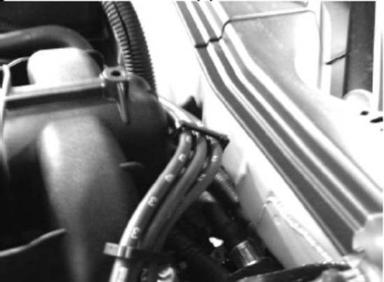
11. Tuck the passenger side plug wires behind the upper intake manifold.
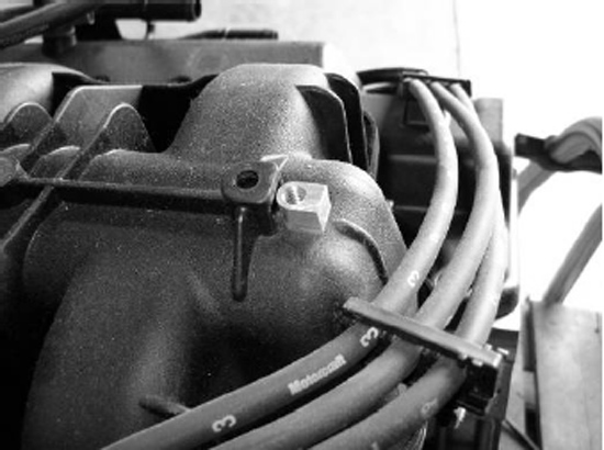
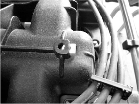
12. Install threaded insert (part# 0511-3500-01) into the upper intake.
13. Remove the top two 8mm throttle body bolts and the oil cap. Some cars may be equipped with an oil filler neck extension. If your vehicle is equipped with this, twist off at base, do not reinstall.
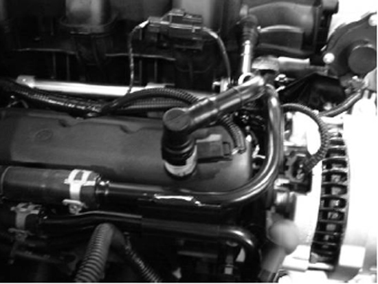
14. Rotate Passenger side EVAC hose as shown.
15. Bend tabs for the ground and wiring harness on the firewall down.
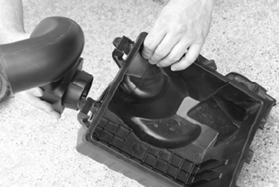
16. Install air box coupler (Part# 0511-3501-01) to engine cover. Note: Clamp on the inside for a cleaner look. Do not over tighten.

17. Attach the Drain tubes (4 – part# 183027) to the engine cover and secure them with the supplied
20. Reinstall air filter housing into vehicle.
21. Place engine cover on engine, insert the supplied ¼”-20X3/8” button head screw at the back of the engine cover and reinstall the two 8mm throttle body bolts. Note: Bracket is slotted for adjustment.
22. Route Mass Air Flow connector through the engine cover and reconnect to sensor.
23. Slide Coupler over Lower Air Tube (part #115053), and tighten clamps. (do not over tighten)
Installing Hood Trim Ring
1. Remove tape from hood. Clean area of hood around the cut opening with Isopropyl (rubbing) Alcohol where Upper Trim Ring will be placed. It is imperative that any wax be removed from the vehicle at the tape contact area for proper adhesion of Trim Ring.
2. Apply 3m Acrylic Bonding tape (part #950015) to bottom side of Upper Trim Ring. Sand area with 80-120 grit sand paper, clean with supplied Alcohol pack and allow time to dry, apply supplied Adhesion Promoter and allow time to dry, apply 3m tape. Press on tape with fingertips to set tape.
3. Peel 3”-4” of the red backing from the Upper Trim Ring (part # 115051) and place in hood opening. When proper placement is achieved, finish peeling the red backing from acrylic bonding tape and press on trim ring to set tape to hood. Make adjustments to engine cover if needed.
4. Raise and prop hood.
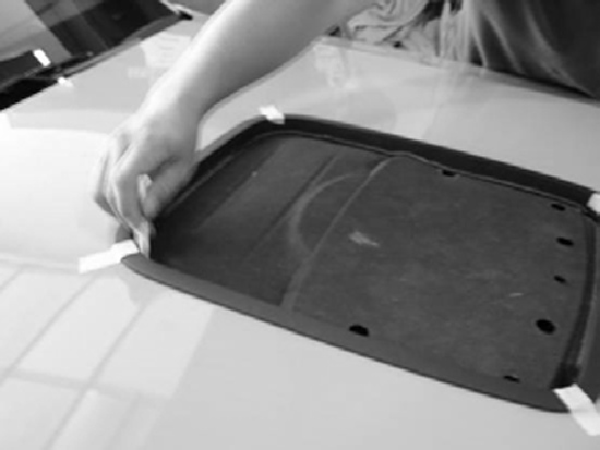
5. Temporarily install hood blanket to bottom of hood using factory fasteners and trace inside of Upper Trim Ring onto the hood blanket. Remove hood blanket and set on bench. (A white grease pen works best.)
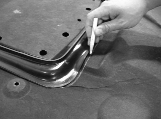
6. With the hood blanket on the bench, line up the Lower Trim Ring (part # 115050) with the line traced from the upper. Now trace the outside of the Lower Trim Ring onto the hood blanket. Note: Trim Ring will follow contour of the hood blanket when properly positioned, the hump is toward the rear. Remove Lower Trim Ring and measure ½” from the outer line toward the center of the hood blanket and mark one more line, this is the line you will cut using a sharp blade. Cut out blanket.
7. Reinstall hood blanket with factory retainers in their proper locations.
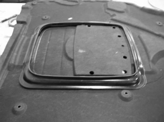
8. Install the Lower Trim Ring onto the Upper Ring flange, squeeze until trim rings snap together. The Lower Trim Ring will hold the hood blanket in place around the opening.
9. There are two 3/32” holes that are predrilled in the front and rear of the Upper and Lower Trim Rings (4 total). Use #183011 rivets to secure the Upper and Lower Trim Rings together.
10. Congratulations your installation is complete!