 FREE 1 to 3-Day Delivery on Orders $149+ Details
SHR Mustang Billet Climate Control Knobs Installation Guide ('07-'08)
Installation Time
30 minutes
Tools Required
- T-9 Torx Bit (included)
- #2 Phillips screwdriver
- Battery Wrenches or terminal removal tool
- Center Punch
- Large pair of straight pliers or Channel-Lock pliers (for alternative installation method)
- 7mm Socket and Driver / Ratchet
- Small prying / pick tool
- Small hammer
- Flashlight
Installation
Attention:Before Starting, read both sets of instructions below and decide which method you would like to use to install your new climate control knobs. Both methods will achieve the same result, and although method #1 is much quicker, it is more difficult to make sure all plastic is removed properly prior to installation of the new control knobs which is important for proper reassembly and function of new Tru-Billet knobs.
Also be aware that the OEM did not design the climate control on 07 models to be field-serviced, and extra care must be taken to insure no damage to unit results during this procedure. Although SilverHorse Racing has tested both procedures with complete success, we are not liable for any damage you may cause to your vehicle while attempting this installation. These instructions should be considered a guide only, and are not written as a replacement for OEM techniques and instructions for vehicle service.
Installation:Method #1
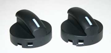
1. With the vehicle off, in park or neutral and with the parking brake set on a flat, level surface, begin by turning all three controls to the 12 o’clock position. Grasp the knobs firmly one at a time with pliers, and pull straight away from the head unit, being careful to not dislodge the shifter or accidentally release the emergency brake. This will break the outer half of the knob away from the inner half, and does require some force. Slight wiggling from left to right may aid in removal. Discard the outer half of the knob after inspecting to see how much plastic remained in the climate control unit. Look at image below to see a broken knob vs. unbroken to see where the breaks will occur. Broken piece is on the right.
2. After removal, shine flashlight into the climate control unit, and using a small pick tool, remove any broken remnants of the outer half of the original control knobs. Looking at each knob will tell you how many pieces you must find in each hole between the inner half of the knob and the climate control housing face. When you are sure you have removed all remnants, you may want to use a small vacuum to double check your work and clear out any remaining plastic bits that were unseen.
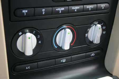
3. Install new knobs, aligning indexing mark (small line engraved onto diameter of knob back ring) with index mark on knob receiving half in head unit, which should be set to the 7 o’clock position to correspond to the knob being at 12o’clock. Push firmly until you hear an audible click, or until knob surface is flush with climate control face and rotating freely like original knobs. Test for proper operation.
Installation:Method #2
1. Turn key to the off position and remove from ignition, making sure vehicle is in park / neutral and the parking brake is set on a flat, level surface. Open the hood and disconnect the battery, negative terminal first, followed by the positive terminal. Let sit for 5 Mins minimum to discharge airbag system.
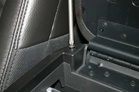
2. Open the center console armrest pad, and locate / remove the two Phillips head screws that retain the upper half of the center console to the lower half. If anything remains in the cup holder, now would be a good time to remove it.
3. If the car is equipped with an automatic transmission, lightly pry on the bezel surrounding the shifter to remove it. If the car has a manual transmission, unthread the shift knob and remove along with the shift boot (it will snap out once the knob is no longer in place.)
4. Once the shifter bezel / boot is removed, the top of the console can be lifted from the rear, and pivoted up from the back to remove it. The console needs to be wiggled around the e-brake arm to remove it – be sure to not to accidentally release the brake while removing the console top. There are six pop-clips retaining the top of the console to the bottom that will unclip for removal. If any of the metal clips stay in the lower half of the console, they will need to be removed and reinstalled on the upper console prior to reassembly.
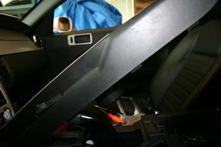
5. With the upper console removed, the two side covers / inner kick panel covers of the center dash can be removed. To remove, pull them straight away from the dash one at a time. This will expose six screws underneath, three on each side which can then be removed with a 7mm socket.
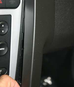
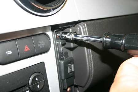
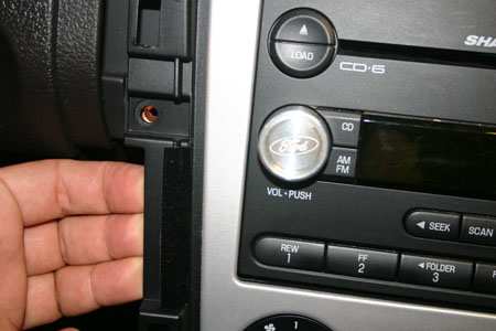
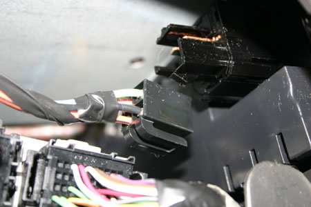
6. Once the six screws have been removed, the stereo & A/C control cover can be removed. To do so, gently pull on the sides of the cover to release the pop clips. Without removing completely, reach around the backside, and release the wiring that goes to the traction control, auxiliary power outlet (cigarette lighter) and the MyColor dash (if equipped). Once the wiring is removed, the center dash cover can be safely removed. The wiring going to the airbag light setup is one of the reasons the battery must be disconnected in step 1.
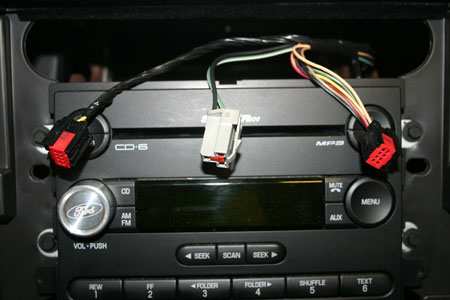
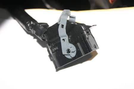
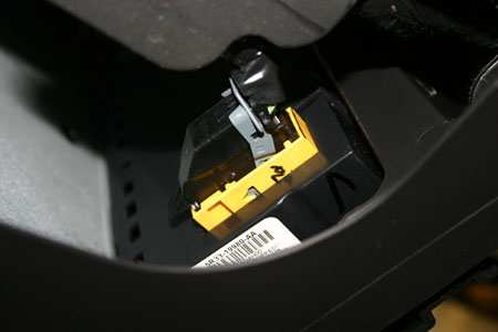
7. With the center kick panel covers removed, there will be access to the wiring to the A/C control unit from each footwell area from the backside. Reaching behind the A/C control, the fan control wiring and the additional wiring control needs to be removed. The fan control is a squeeze and release type plug, while the remaining plug is retained with a pivoting latch mechanism. Once both plugs are disconnected, the screws holding the A/C control can be removed, and the A/C head unit removed from the vehicle.
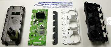
8. On a clean workbench, use the supplied T-9 Torx bit to disassemble the head unit by unscrewing the six T-9 screws. Be careful to lay out the head unit components so that they can be reassembled in the same order after the new knobs have been installed. All knobs should be in the 12 o’clock position before disassembly. Remove the back cover, carefully remove the circuit board by handling on its edges, remove the button soft panel, and the white plastic plate, being careful to unclip the small snap clips as required.
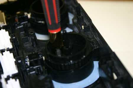
9. The front half of the knob can now be unsnapped from the balk half. All three forward halves are the same, it is the balk half which is individual to the position / function, so be sure to keep them in order or do this one knob at a time. Normally, removal of the front half of the knob will crack it at the retaining clip, as they were not meant to be a maintenance (i.e. able to be disassembled) item. This will not harm the back half of the knob if done correctly. Using a small punch, impact the outer half of the knob from the backside to break it away from the back half. Do this one knob at a time. Be careful to not damage the back half of the knob assembly, as it will be re-used in the coming steps.
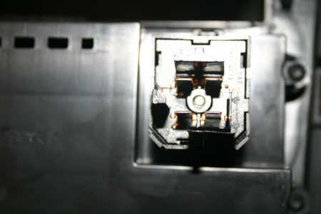
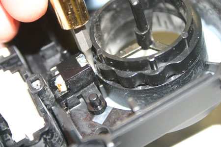
10. Using a small pick or screwdriver, depress the white ratcheting stop on the bottom of the back half of the knob to remove from the front of the control unit. There are clips retaining the 3-pronged back-half in the hole, so the will need to be wiggled out. Once removed, use a small cloth to wipe out any plastic left by the original knob, and re-assemble the back half to the face of the climate control unit, insuring it is in the same location (rotation) as when removed. If unsure, rotate the half until the index mark on the back half is in the 7 o’clock position. This would correspond to the knob being in the “up” or 12 o’clock position.
11. Install the new knobs, making sure they fully engage the back half of the knob assembly and snap into place. There is an index mark machined into the knob to correspond to the index mark on the back half of the assembly to aid in assembly – it is a small line, not completely cut through the back ring area. Check for free rotation throughout their intended range of motion, and then return them tithe 12 o’clock position for re-assembly.
12. Reassembly of the head unit is the reverse of disassembly. Once you are confident with the head unit and buttons on the assembly, reinstall in the car and reconnect the wiring, making sure to latch the connector on the passenger side and clip in the fan control on the driver’s side.
13. Continue reassembly of the interior of the car, as it is the reverse of steps 7 to 1. Start vehicle when complete and check for proper operation of the A/C controls and other center console functions.
Installation instructions provided by SilverHorse Racing products.
Related Guides
-
Installation
-
Installation
-
Installation

