FREE 1 to 3-Day Delivery on Orders $119+ Details
Best Sellers


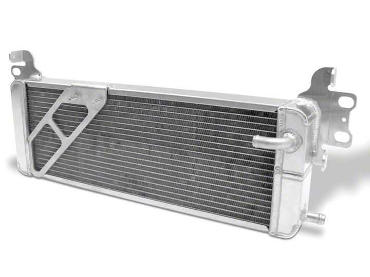
How to install a AFCO Double Pass Heat Exchanger on your Mustang
Shop Parts in this Guide
Installation
WARNING:
1. Radiator fluid must be handled properly. Please observe local ordinances with regards to handling and disposal.
2. Allow vehicle and components to cool a minimum of 1 hour before handling.
3. Never attempt to open the radiator cap when hot.
4. Do not allow any tools or limbs to contact fans—SERIOUS INJURY MAY RESULT.
5. Always follow directions and disconnect the battery before attempting installation.
6. AFCO is not responsible for personal injury or damage to vehicle resulting from improper installation of this product.
7. Due to vehicle variations / tolerances it is ultimately up to the installer to determine proper installation.
1. Remove the 8 clips that retain the upper radiator shroud. Remove the shroud.
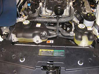
2. Remove the coolant tank cap from the heat exchanger coolant tank.
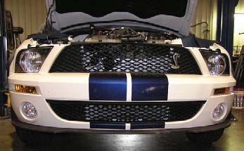
Front Bumper Cover Removal
3. Remove the two front wheels and set aside.
4. Remove the 7 screws from the lower splash guard using a 5.5mm socket and remove the splash guard.
5. Remove the 10 bolts from the lower lip air dam using a 10mm socket. Remove the air dam.
6. Remove the 10 screws and clips from the fender well splash guards. Pull the splash guards back from the front bumper and remove completely.
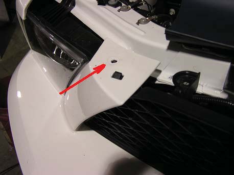
7. Remove the two nuts that retain the front bumper to the front fender on each side. These nuts are located at the very back corners of the bumper and are accessible from inside the fender wells.
8. Unclip the three electrical connectors on each side that attach to the fog lights, turn signals, and parking lamps.
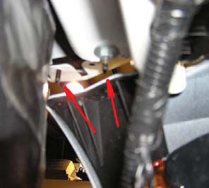
9. Remove two bolts retaining the top of the bumper to the core support.
10. Lift the top “ears” of the bumper up and over the tabs. Then, slide the whole bumper cover forward and off of the vehicle.
11. Grab the foam bumper core and pull straight out to free the 4 plastic clips. Be careful not to damage the clips or the foam core.
Heat Exchanger Removal
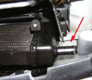
12. Drain the coolant from the heat exchanger by removing the lower hose on the passenger side of the stock unit.
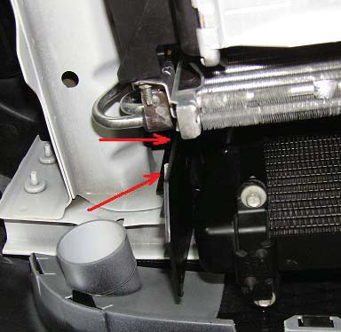
13. Remove the 4 nuts that secure the heat exchanger mount to the vehicle’s frame.
14. From above, unclip the electrical connector at the factory pump attached to the heat exchanger.
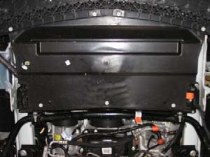
15. Unclamp and remove the hose connecting the pump to the surge tank.
16. Remove the 4 plastic clips attaching the plastic shroud to the heat exchanger.
17. It is recommended at this point that the horns be removed from the vehicle to allow ease of removal of the heat exchanger without damage to the AC condenser.
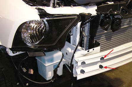
18. Using a 13mm deep well socket, remove the two bolts closest to center on each side that attach the front bumper to the frame.
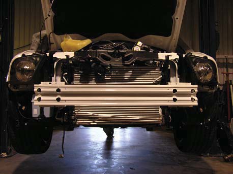
19. At this point, the factory heat exchanger and bracket can be lifted up and out of the vehicle.
20. Remove the pump from the factory bracket and remove any hoses connected to it.
AFCO Heat Exchanger Installation
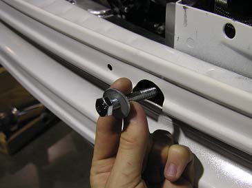
21. Install the four supplied 8mm x 50mm long bolts and washers in place of the bolts removed in step 19. Screw them in until they protrude about 3/4” from the opposite side.
22. Using a ½” wrench, attach the stock pump in the same orientation as stock to the AFCO heat exchanger using the supplied nuts.
23. Connect the supplied 90o rubber hose between the pump outlet (facing down) and the heat exchanger inlet (90o tube). Trimming of the hose may be required. Clamp both ends with the supplied hose clamps.
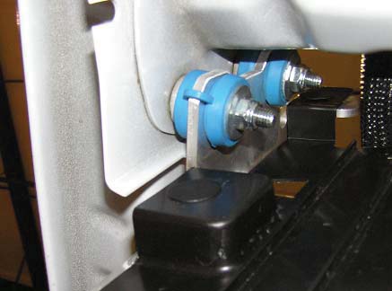
24. Snap the four supplied mounting grommets, washer side toward rear of vehicle, into the mounting holes on the heat exchanger brackets.
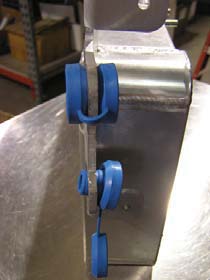
25. Slide one of the supplied aluminum bushings into each blue grommet.
26. Slide the heat exchanger up from the bottom and place on the mounting studs.
27. If the pump outlet or hose is too close to the AC condenser, rotate the pump in its rubber hanger until sufficient clearance is obtained. Lubrication of the rubber piece may be required in order to rotate the pump.
28. Finish threading the bolts installed in step 22 completely into the bumper and tighten. Make sure that the washers do not get caught on the lip inside of the bumper and that they are resting flat.
29. Secure the heat exchanger using the four supplied Nylock nuts. The blue grommets should crush approximately 1/16”. Do not over tighten the nuts.
30. Install the plastic shroud on the outside of the AFCO brackets using the four factory clips.
31. Re-attach the factory hoses to the lower heat exchanger outlet and the pump inlet using the factory clamps.
32. Re-connect the electrical connector to the pump. Secure the wire-loom to the upper hose on the heat exchanger using the supplied wire ties.
33. Verify all bolts, nuts, and hose connections.
34. Fill the system and surge tank using the recommended OEM coolant.
35. Reconnect the negative battery cable, start the vehicle, and allow the car to idle until warm. The heat exchanger pump will not turn on until the air charge is warm.
36. Once the pump turns on, the level in the surge tank will drop rapidly. Continue adding coolant until at the recommended level. This system will hold approximately 1.5 gallons of coolant.
37. Continue to run the vehicle for 5 minutes to verify all air is purged from the system. Check system for leaks while waiting.
38. Once system is checked, install the bumper, splash guards, air dam, and wheels in the reverse of removal.