FREE 1 to 3-Day Delivery on Orders $149+ Details
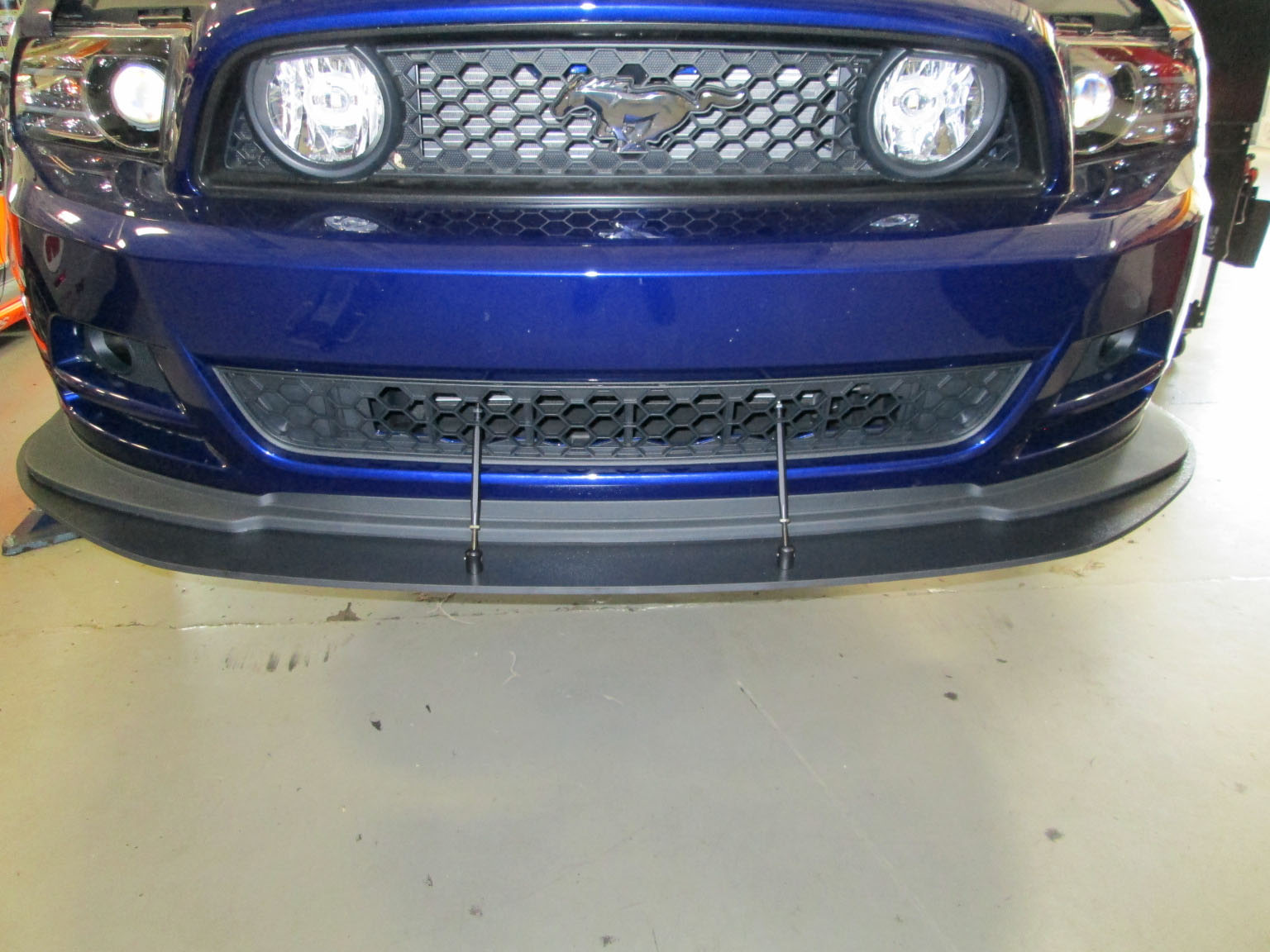
How to Install a Ford Racing BOSS 302 Laguna Seca Front Splitter on your 2013 Boss 302, GT and V6 Mu
Please visit www.fordracingparts.com for the most current instruction information
! ! ! PLEASE READ ALL OF THE FOLLOWING INSTRUCTIONS CAREFULLY PRIOR TO INSTALLATION. AT ANY TIME YOU DO NOT UNDERSTAND THE INSTRUCTIONS, PLEASE CALL THE FORD RACING TECHLINE AT 1-800-367-3788 ! ! !
PLEASE NOTE: THIS SPLITTER KIT IS INTENDED FOR USE ON CLOSED COURSES ONLY AND IS NOT STREET LEGAL. THIS SPLITTER KIT MUST BE REMOVED PRIOR TO DRIVING ON PUBLIC ROADS. FORD RECOMMENDS THE STANDARD SPLITTER ONLY FOR USE ON PUBLIC ROADS.
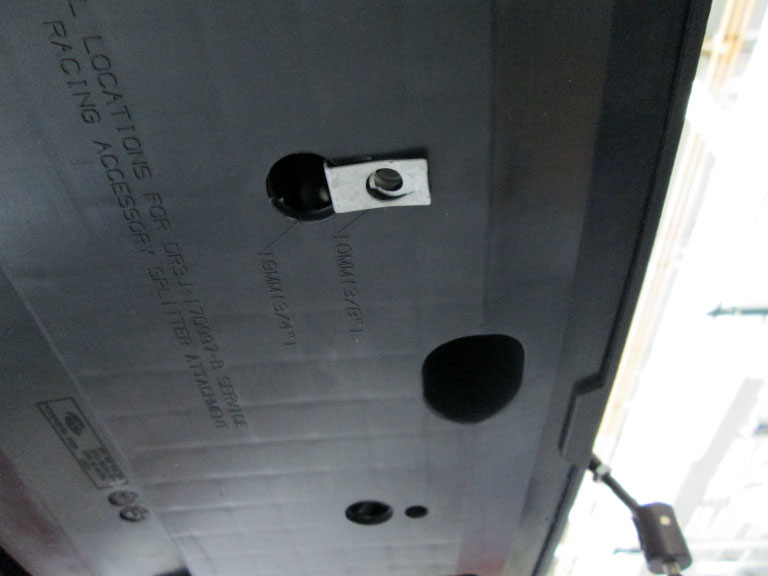
NOTE: To install splitter on 2013 BOSS 302 Mustang requires installation of M-17A626-MB bumper bracket.
NOTE: To install splitter on 2013 Mustang GT/V6 requires M-16601-MBKIT prep kit.
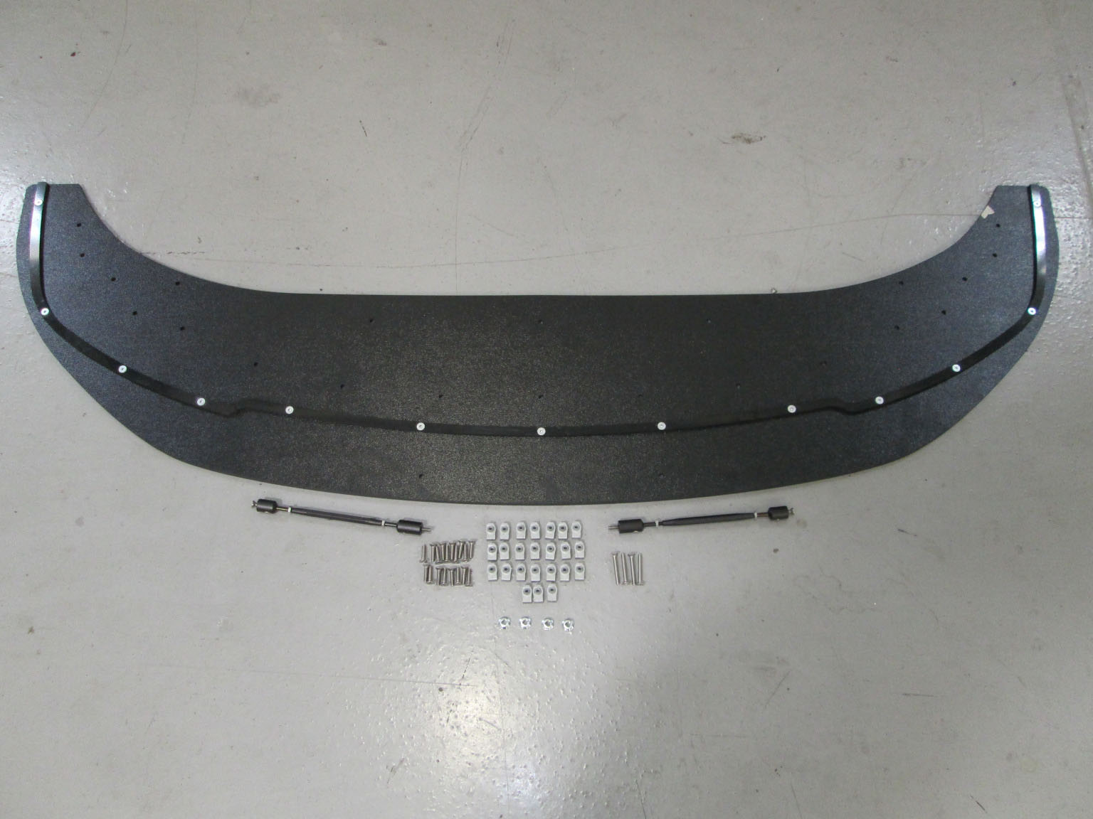
SPLITTER KIT:
Quantity Part Name
1 Splitter
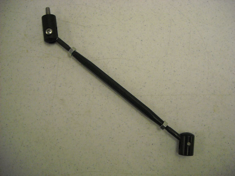
2 Splitter support rod assembly
18 M8 X 25mm bolt
4 M8 X 45mm bolt
22 J-Nut
N0TE: Additional items required during install include RTV Silicone, Blue thread locking compound, and Red thread locking compound that are not included in kit M-16601-MBA.
INSTALLATION INSTRUCTIONS:
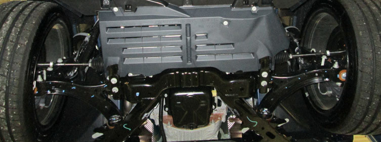
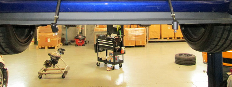
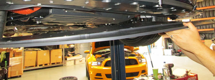
STEP 1: Support the vehicle to gain access to the undercarriage.
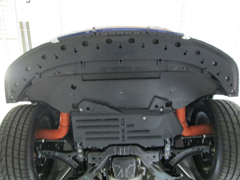
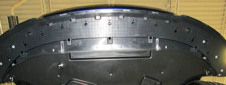
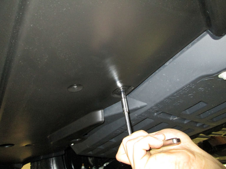
STEP 2: Remove the (4) bolts on the front edge of the lower deflector.


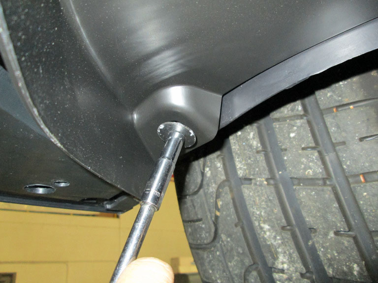
STEP 3: Remove the (2) outboard bolts securing the outside of the deflector.


STEP 4: Remove the (3) rearward bolts securing the deflector.


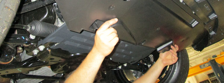
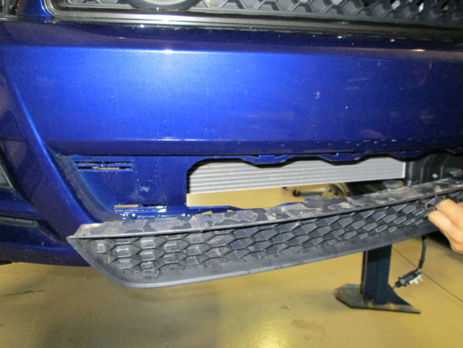
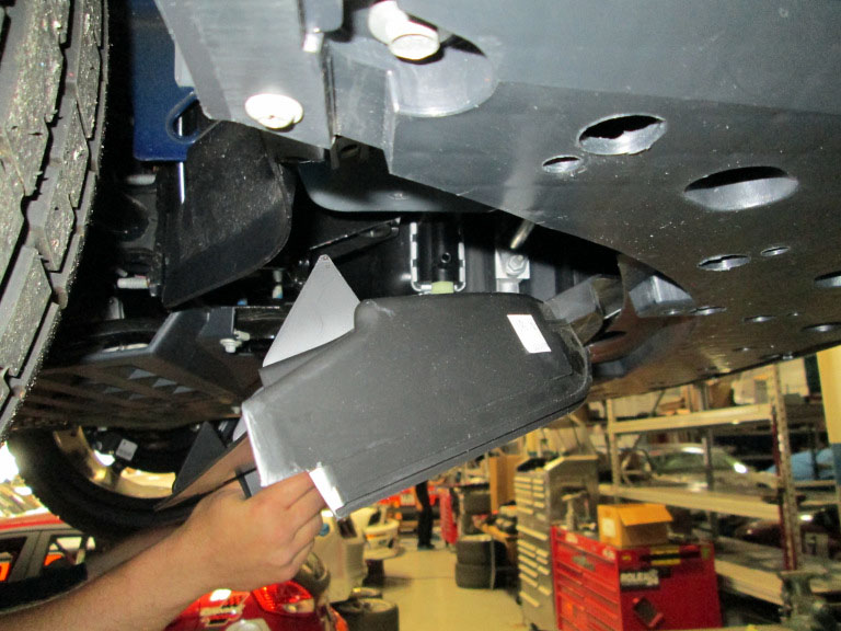
STEP 5: Remove the lower deflector from vehicle.

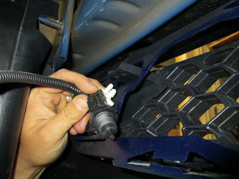
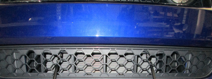
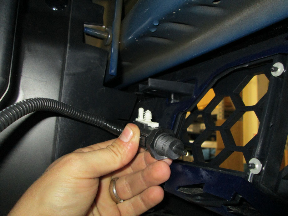
STEP 6: From the backside of the fascia, gently unclip the temperature sensor from the lower grille.
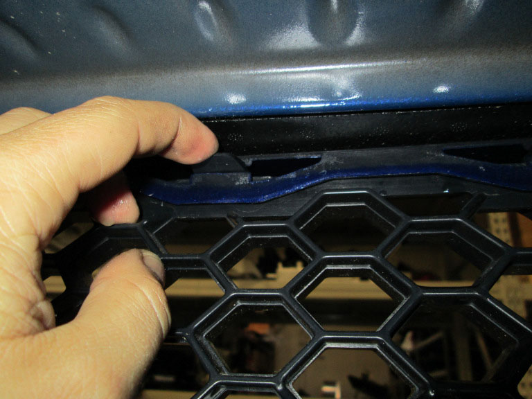
STEP 7: From the backside of the fascia, gently unclip the lower grille retaining clips from the fascia (12) locations. Remove the lower grille from the vehicle.
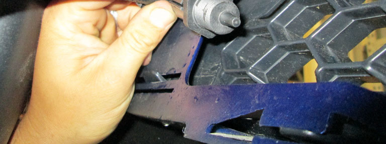
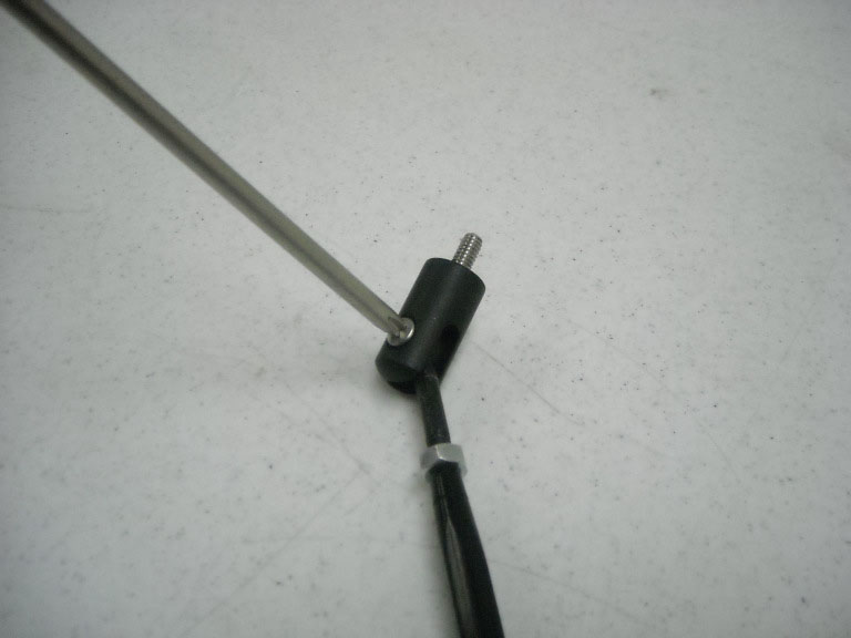
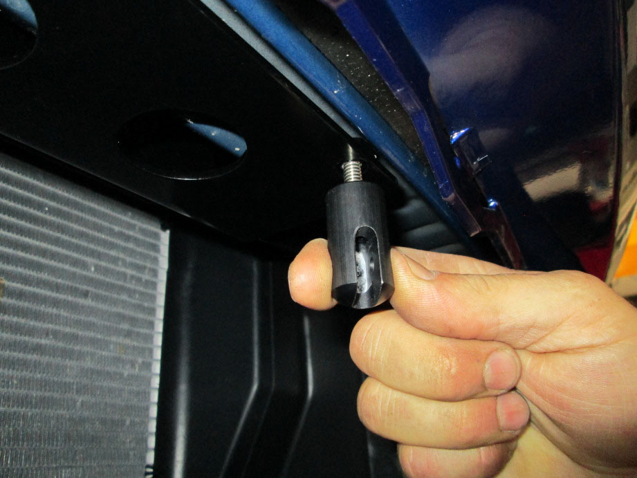
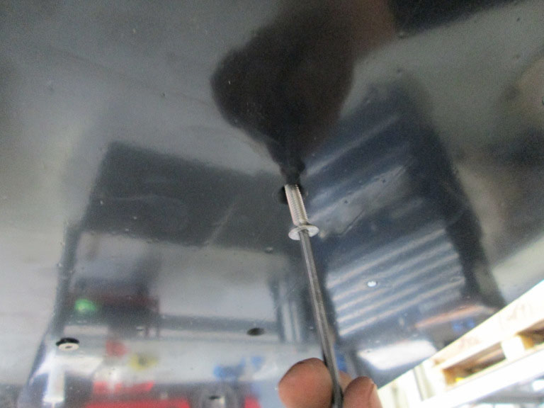
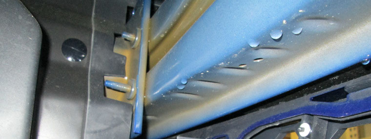
STEP 8: Remove the (2) Phillips screws that retain the support rod to the stanchions and separate.
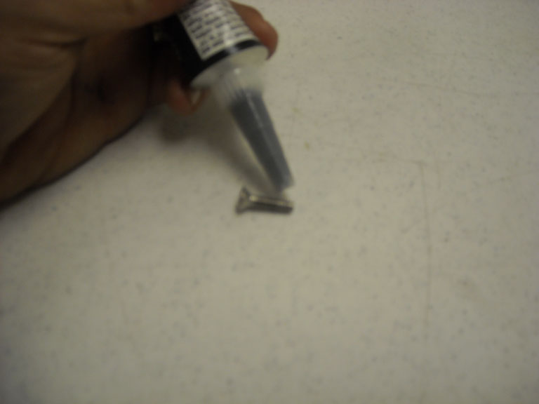
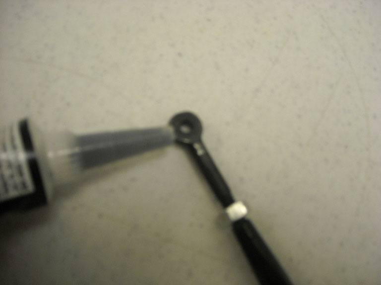
STEP 9: Apply RTV Silicone to the (2) Phillips screws covering threads and fill both eyelets.
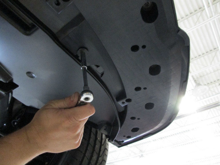
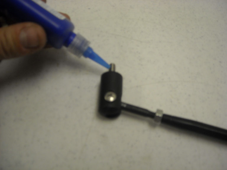
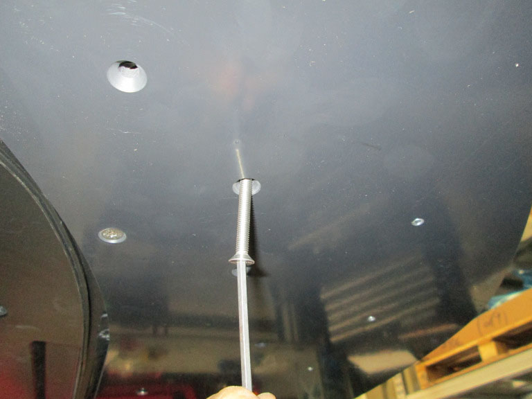
STEP 10: Apply a liberal amount of Blue thread locking compound on upper stanchion thread and proceed with installation. Install upper stanchion without support rod into the bumper bracket and tighten. This is done from below the vehicle, behind the lower grill.
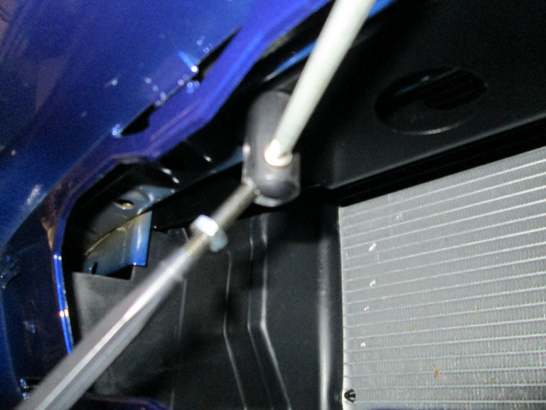
STEP 11: Install the support rod back into the stanchions, insert (2) Phillips screws and tighten. Clean any excess RTV Silicone from assembly.
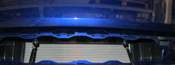
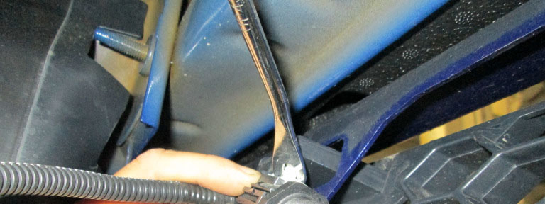
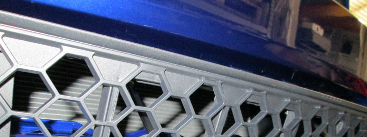
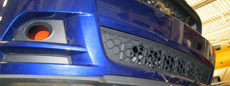
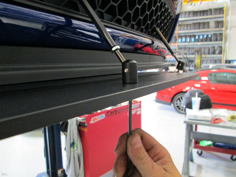
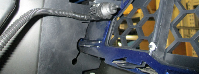
STEP 12: Insert the support rods through the grille openings shown below and align grille with the fascia.
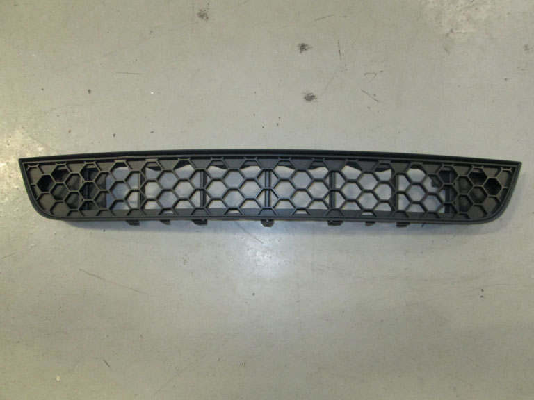
STEP 13: Insert the new lower grille insert by aligning the grille clips with the receiving locations in the fascia, gently push into place verifying the (12) retaining clips are securely attached.
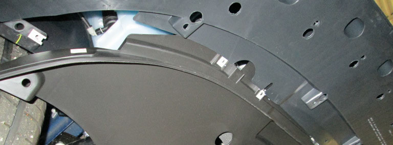
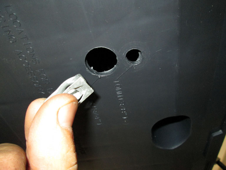
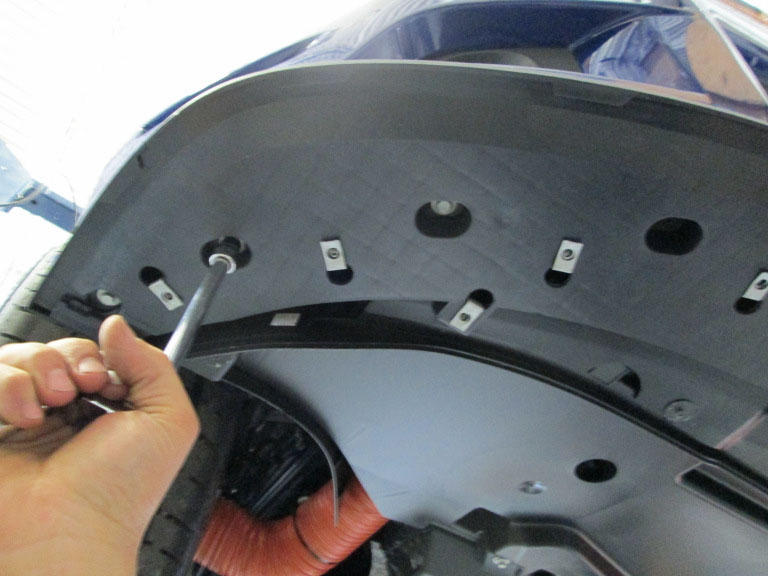
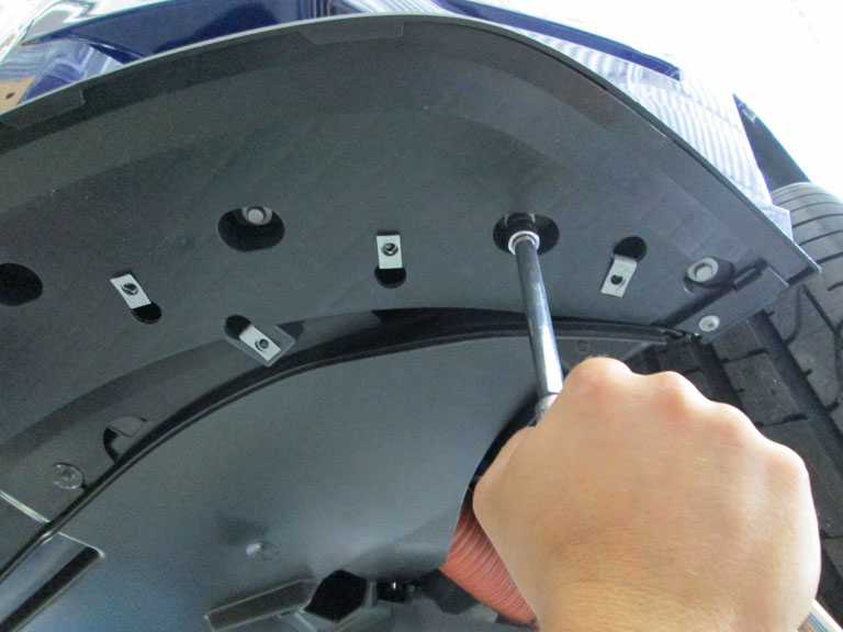
STEP 14: Install (18) J-Nuts into the provided locations.
STEP 15: Remove (4) splitter to fascia bolts.
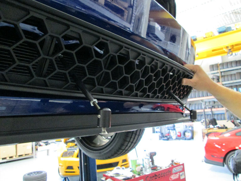
STEP 16: Place splitter against the bottom of the fascia, install (4) M8 x 45mm bolts into the locations noted in STEP 15 and torque bolts to 28 in.-lb.
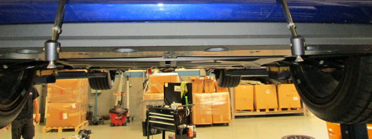
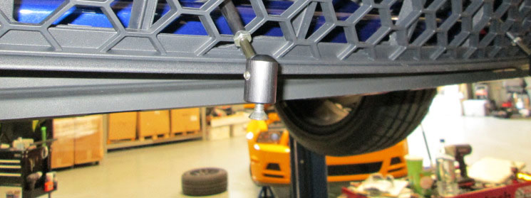
STEP 17: Install the splitter support rods to the splitter and torque bolts to 28 in.-lb.
STEP 18: Install the remaining (18) M8 x 20 fasteners into the existing holes on the splitter. Torque each fastener to 28 in.-lb. beginning with center-most fastener and working outward on both sides.
STEP 19: Install the temperature sensor by clipping it into the provided location on the backside of the lower grille insert.
STEP 20: Install the deflector by sliding it forward verifying that its forward most lip is above the newly installed splitter.


STEP 21: Using the bolts removed in STEP 4, install the (3) rearward bolts and torque to 15 in.-lb.

STEP 22: Using the bolts removed in STEP 3, install the (2) outboard bolts and torque to 15 in.-lb.


STEP 23: Using the (4) of the bolts removed in STEP 2, install the (4) bolts on the front edge of the deflector and torque to 15 in.-lb.