 FREE 1 to 3-Day Delivery on Orders $149+ Details
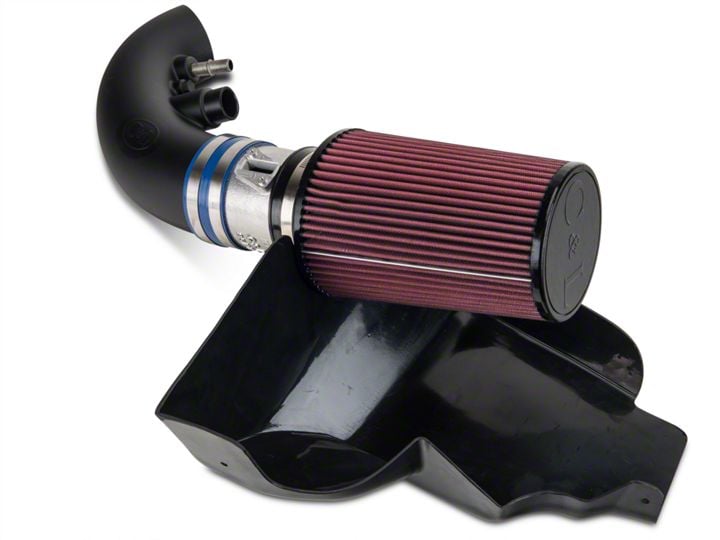
How to Install a C&L Cold Air Intake on Your 2011-2012 GT Mustang
Installation Time
1 hours
Tools Required
- Flat Blade Screwdriver
- Socket Wrench with Extension
- Socket sizes (8mm, 10mm, 13mm)
- Channel Lock Wrench
- Socket driver for the supplied T-20 Torx bit
Shop Parts in this Guide
Installation
**IMPORTANT**
- This modification requires a re-tune of the computer memory. If this modification is performed prior to re-tuning the computer, do not run the vehicle under heavy load or high rpm until the re-tuning is completed.
- Do not use a generic cold air intake tune with the C&L CAI kit. Use only a tune provided from a knowledgeable manufacturer.
- Do not use the OEM factory screws with the C&L MAF (Mass Air Flow) housing. Use only the screws provided with the C&L CAI kit or damage can occur.
Prepare Engine Compartment:
Part 1: Remove the strut tower brace (if equipped on vehicle). The strut tower brace is removed by loosening and removing the (4) strut nuts on both the passenger and driver sides. Remove all (8) nuts with a 13mm deep socket wrench, lift up the brace and place the strut tower brace in a safe location.
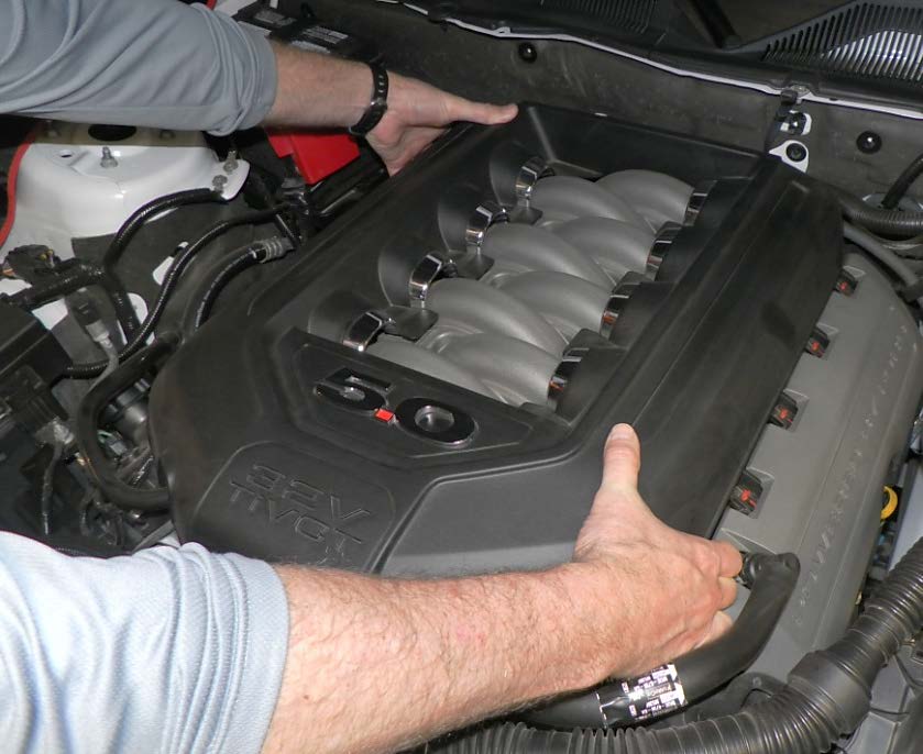
Part 2: Remove the stock engine cover. The engine cover is held in place by (4) rubber mounts (2 on each side). To remove the cover, lift straight up on the plastic cover starting at the front side and moving toward the back. Set the cover in a safe place.
Remove Stock Air Intake:
Part 1: Loosen the clamp holding the black stock air inlet tube to the throttle body.
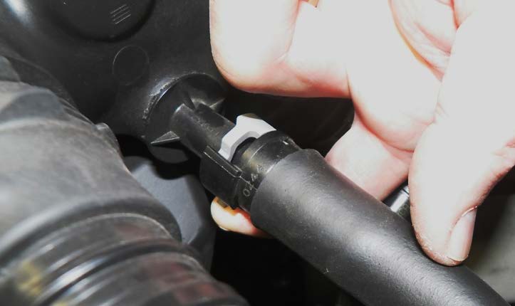
Part 2: Remove the vacuum hose connecting the valve cover to the stock black air inlet tube. On the fitting that attaches the hose to the air intake tube, there is a small tab holding the fitting in place. Move the tab with your finger and the fitting will pull away easily from the tube connector.
Part 3: **Automatic Transmissions Only** If you have an automatic transmission, there will be another smaller fitting next to the valve cover vent tube. To remove it, push down on the yellow tab while pulling away from the pipe fitting.
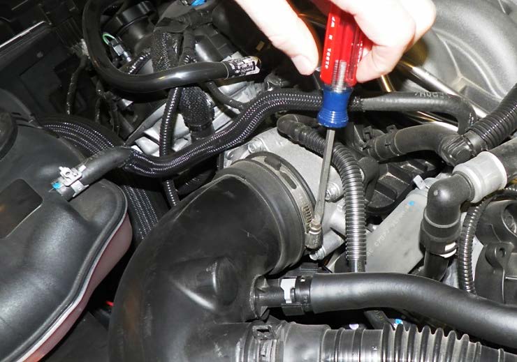
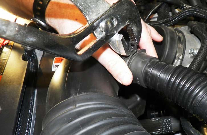
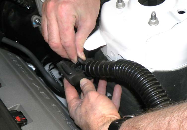
Part 4: Remove the noise transmission tube from the stock air intake tube by squeezing the spring clamp with channel lock pliers or vice grip tool. The spring clamp will “lock” to the loose position if squeezed completely.
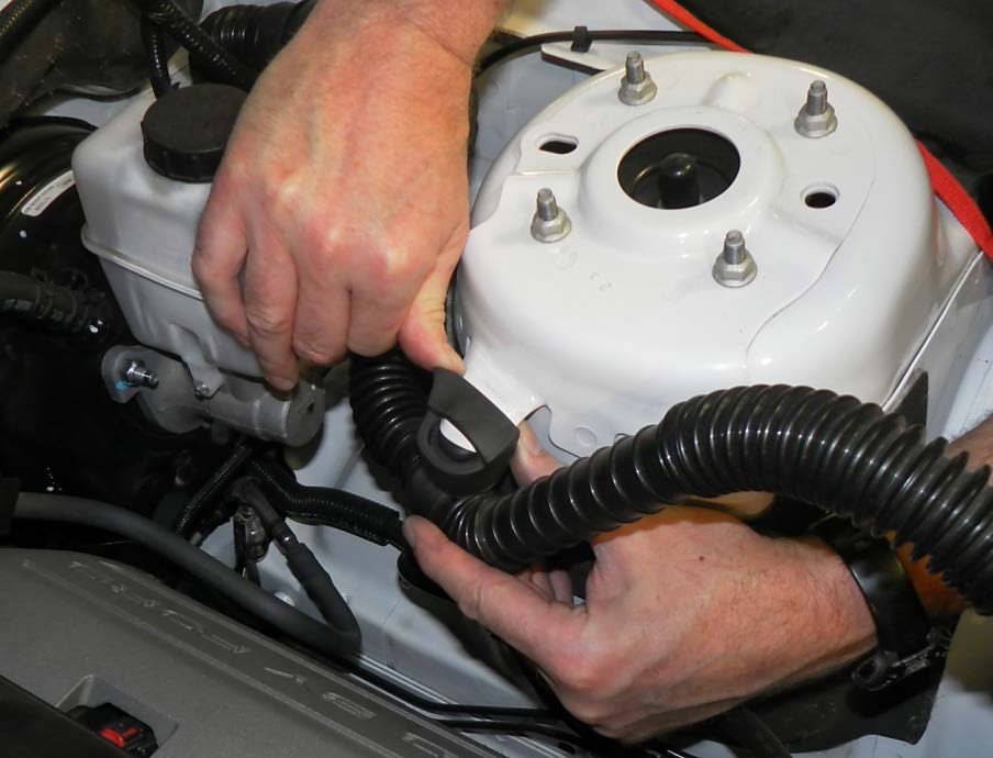
Part 5: Disconnect the flexible noise tubing from the factory air box by opening the rubber clamp that wraps around the tube. Move the noise transmission tube by pulling it away from the triangular shaped mount on the driver side strut tower.
Remove Stock Air Box:
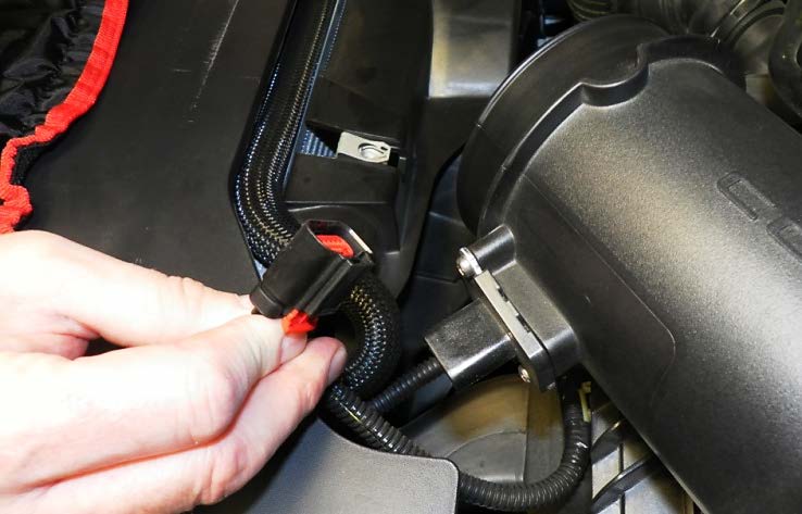
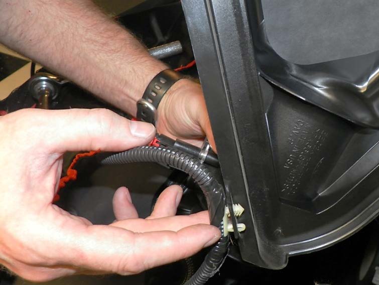
Part 1: Disconnect the MAF (Mass Air Flow) sensor wiring connector on the front of the stock air filter housing. To disconnect it, slide the red tab on the bottom of the connector to unlock the connector and pull it toward the front of the vehicle.
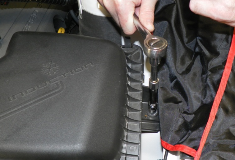
Part 2: Located between the driver side fender and the stock air box, you will see a 10mm bolt fastening the air box to the car. Remove this bolt and set aside for re-use.
Part 3: Separate the MAF wiring harness from the factory air box by pressing the nylon inserts that attach the harness to the air box back through the holes.
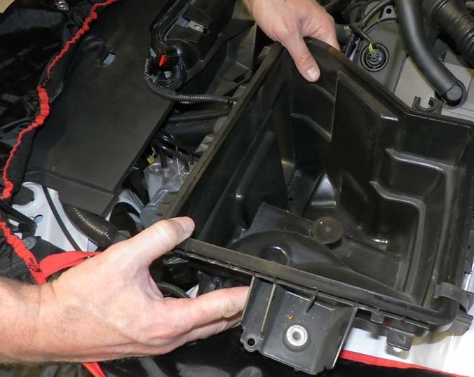
Part 4: Lift the stock air box slightly upwards and toward the rear of the vehicle. This will release the rubber feet that hold it to the vehicle. Slide the lower half from the fresh air feed that enters from between the headlight and radiator support. Remove the entire stock air box from the engine compartment.
Assemble New Housing:
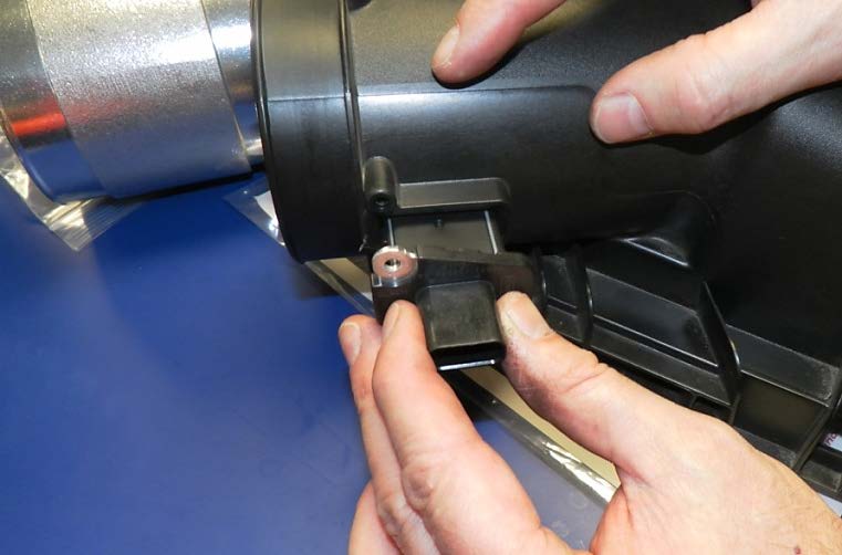
Part 1: Using a T-20 Torx bit or Torx screwdriver, remove the (2) screws that fasten the factory air meter-sensor to the stock air box. Carefully slide the sensor straight out of the housing. NOTE: Be sure to include the rectangular rubber seal that typically comes out attached to the sensor cartridge. This creates a seal between the sensor cartridge and the new housing.
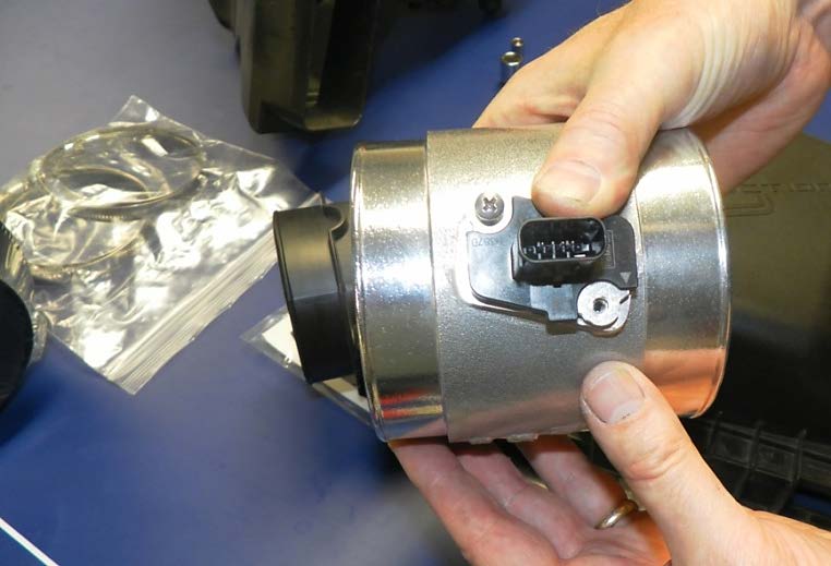
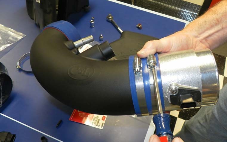
Part 2: Examine the silver aluminum C&L housing provided in the kit. If there are screws in the housing, remove them and set aside. Carefully insert the sensor cartridge into the aluminum C&L housing. When properly oriented, the sensor screw holes will line up correctly. Using the screws provided in the kit (not the factory screws), tighten the sensor cartridge.
Part 3: If not pre-attached in the kit, attach the C&L airflow housing to the round end of the inlet tube using the supplied 4” hose clamps. For proper orientation, the sensor should be pointing towards you (or front of vehicle) and the C L stamp on the housing will be facing down. NOTE: Be sure to press the silver housing flush to the black MAF body.
Install CAI Shroud:
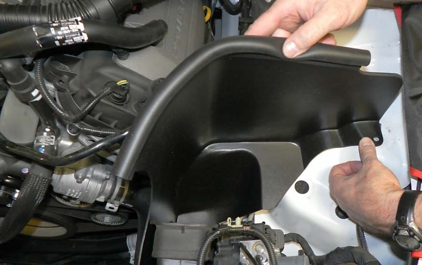
Part 1: Place the black filter shroud into the engine compartment by lowering the “scoop” portion behind and under the rubber fresh air intake feed. Locate the original 10mm bolt hole and re-use the factory bolt to secure the shroud to the vehicle. NOTE: An optional mount is available on the bottom scoop of the shroud. Using it requires drilling a small hole into the vehicle. This installation did not use the additional support.
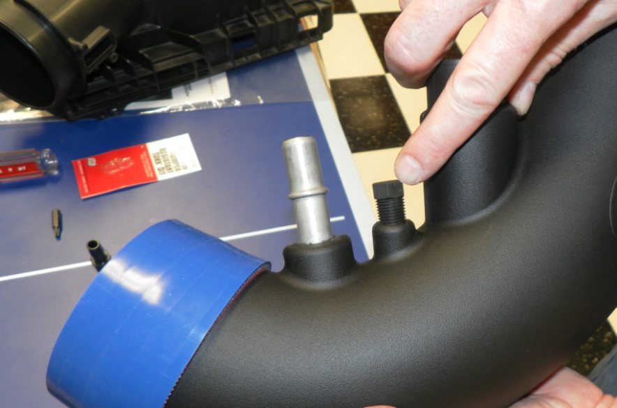
Part 2: There are (2) black tapered fittings supplied in this kit. Manual transmission vehicles will use the supplied nylon plug to cover the threaded hole in the black inlet tube; Automatic vehicles will use the barbed nipple fitting. Using a wrench, tighten the proper fitting completely to the tube for a proper seal (no threads will be visible).
Install CAI Assembly:
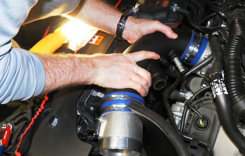
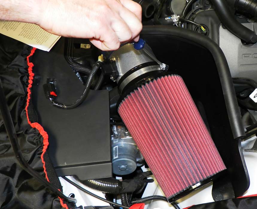
Part 1: Place the (2) provided stainless steel hose clamps over the end of the inlet assembly. Lower the inlet assembly into the engine compartment and slide the blue silicone hose over the throttle body. Tighten the clamp over the throttle body but leave the inlet tube clamp slightly loose for adjustments.
Part 2: Slide the C&L filter over the aluminum housing of the new MAF body. Orient the hose clamp for easy access to tighten. NOTE: At this point adjustments can be made; however, if the filter is bumping against the ABS lines, additional clearance can be made by bending the line slightly toward the front of the vehicle. This was not necessary on this installation.
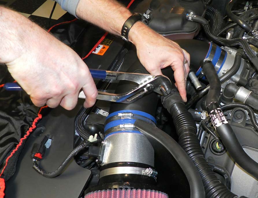
Part 3: Re-insert the factory round noise-transmission tube into the new inlet pipe assembly. Slide the hose entirely over the connector. Use a channel lock wrench to secure the factory spring clamp.
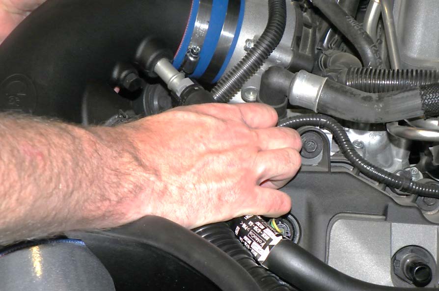
Part 4: Reconnect the valve cover vent tube on the new inlet tube. It will be secured by the locking tabs and click in place. NOTE: If there is difficulty or resistance connecting the vent tube, disconnect the tube from the valve cover and connect the inlet tube first, then re-connect the tube to the valve cover.
**For Automatic Transmissions Only** Re-use the original rubber hose that attached to the factory inlet tube. Pull back the plastic conduit and cut the hose just after the factory nylon release fitting. The exposed 3/8” rubber tubing will then slide over the barbed nipple previously installed.
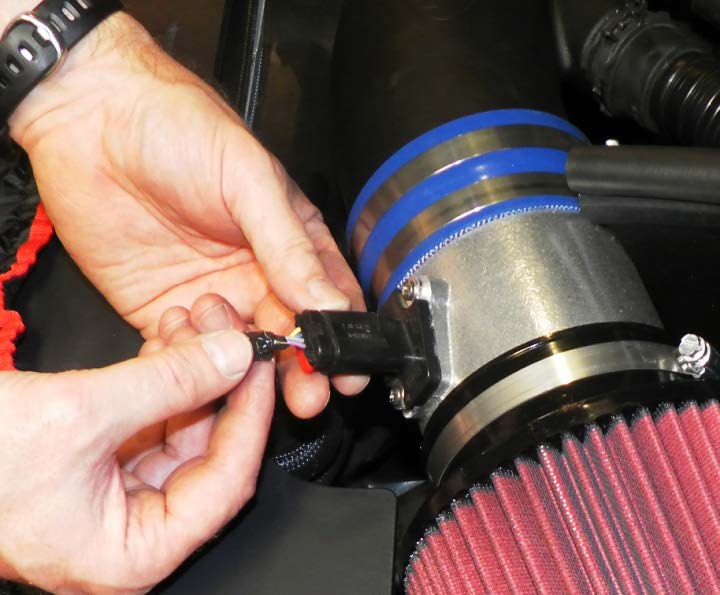
Part 5: Re-attach the MAF (Mass Air Flow) sensor wiring connector to the sensor cartridge located in the aluminum C&L housing. Slightly rotate the housing downwards so the connector is not protruding and susceptible to damage.
Part 6: Re-attach and adjust the triangular rubber mount on the noise transfer hose to the driver side strut tower. The rubber mount will need to be detached and shifted a couple inches toward the front of the vehicle for proper fitment.
Part 7: Once all the fitment and adjustments are made, tighten all hose clamps firmly. Re-install the factory engine cover. Re-attach the strut tower brace if equipped.
Part 8: Remember to properly tune the car before using.
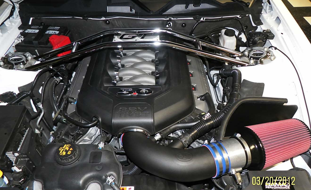
Completed Installation:
Installation Instructions written by AmericanMuscle customer Tony Georgeson 4.13.12

