FREE 1 to 3-Day Delivery on Orders $149+ Details
How to install a Ford Racing Coyote 5.0L 4V Crate Engine Control Pack on your Mustang
Installation Time
3 hours
Tools Required
- Wire Strippers
- Digital Volt/Ohm Meter
- Solder Gun / Solder
- Electrical Tape / Shrink Tubing
- Hand Drill
- Hole Saw
- Utility Knife
Shop Parts in this Guide
Installation
1.0 INTRODUCTION
This kit was developed by Ford Racing to allow performance enthusiasts to easily install today’s modern muscle into street rods from yesterday. We have developed this system to take the complexity and mystery out of installing a Mustang Electronic Throttle Control (ETC) engine into your vehicle. NOTE: This system does not support cruise control.
2.0 OVERVIEW
This booklet provides a step by step guide for the preparation and installation of the controls pack. Please read the instructions thoroughly before starting the installation. If you have any questions, contact Ford Racing Technical Support at (800) 367-3788.
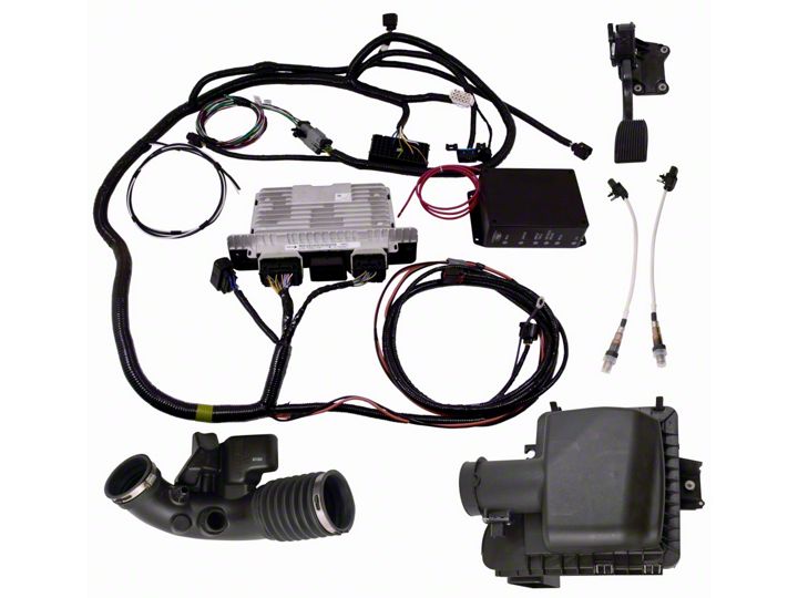
3.0 COMPONENTS INCLUDED
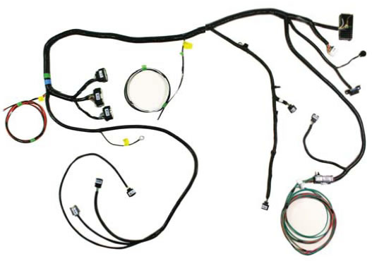
3.1 Cowl Wiring Harness
CM-14A006-A5LB
This harness is labeled and includes all connections required to power up and run your engine equipped with a 2011 or newer factory engine harness.
3.2 Ford Racing Power Distribution Box
CM-14A068-B
The FRPDB connects directly to the CM-14A006-A5LB wiring harness. The FRPDB contains all relays and fuses needed for engine, air conditioner and cooling fan control. The FRPDB may be mounted either in the passenger compartment (preferred) or in well ventilated under-hood locations away from direct sources of heat such as exhaust headers.

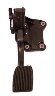
3.3 Accelerator Pedal
BR3Z-9F836-D
This pedal is required for correct electrical interface with the PCM. The engine will not operate correctly without this exact pedal.
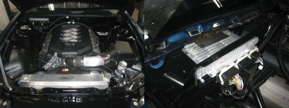
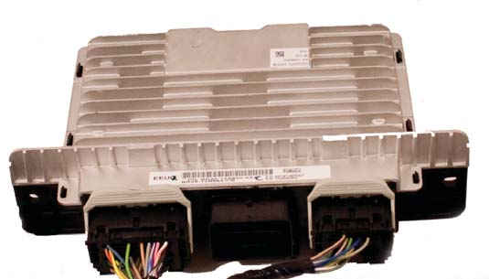
3.4 Powertrain Control Module (PCM)
CM-12A650-A5LA (5.0L 4V)
Commonly referred to as the engine computer, or ‘brain’, this PCM is calibrated for operation with a stock BR33-9600-BC air cleaner assembly (included with this kit) and ‘Return Style’ fuel system as shown on page 14. The PCM is designed for under-hood mounting but may also be located in the wet cowl/wiper motor area or passenger compartment of the vehicle if desired. Wiring modifications may be required to support location of the PCM in either of these two areas. The pictures below show an example of the PCM installed in the wet cowl area.
PCM Calibration Application Notes:
- The calibration provided in this PCM will NOT work with the ‘Returnless’ fuel system as used on factory Mustang vehicles. Use of a return style fuel system is required. Refer to section 9 of this manual for more information on fuel system requirements for this PCM.
- The Air Filter Assembly with Integral Mass Air Flow Sensor included with this kit must be used to achieve acceptable engine performance. Refer to section 3.6 for more information about Air Inlet System requirements.
- Premium Fuel Only (91 Octane or higher).
NOTE: Due to the fuel system requirement described above, installation of this PCM in ANY Production Mustang vehicle will result in a no-start condition!
3.5 Universal Exhaust Gas Oxygen Sensor (UEGO)
8F9A-9Y460-EA
Two UEGO sensors provide wide range feedback to the PCM for closed loop air fuel ratio control.
* Apply a light coat of anti-seize lubricant to the threads of the UEGOs before installing. This lubricant will damage the sensor element so make sure no lubricant comes in contact with the sensor element. Tighten to 48 Nm (35 lb-ft).
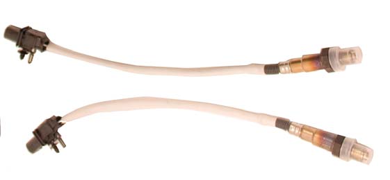
The engine harness and controls package M-6017-A504V is designed to operate with the UEGO sensors in the 2011-2012 Mustang GT stock locations. Moving the UEGO sensors to alternate locations can result in the need to recalibrate the PCM.
Here are some tips if sensors have to be relocated.
The best option is to locate the sensor so it is sampling from all 4 cylinders and at a distance that does not require modification of the UEGO harness.
NOTE: Modification of the UEGO harness can affect function of UEGO sensor.
If your header design will not allow you to sample all 4 cylinders without UEGO harness modifications, a better alternative is locating the UEGO sensor to sample from a single cylinder.
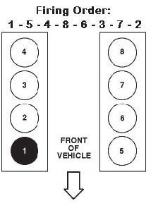
The cylinders that have (on average) the closest A/F ratio to the bank average are cylinder #4 (on bank 1) and cylinder #7 (on bank 2). If that's not possible due to packaging constraints, the next best choices are cylinder #3 (on bank 1) and cylinder #8 (on bank 2). Calibration required!
3.6 Air Cleaner Assembly with Integral Mass Air Flow Sensor
BR33-9600-BC
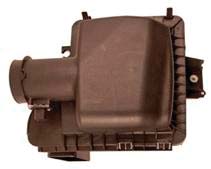
IMPORTANT NOTE: The calibration of the PCM you have received requires use of this air box/MAF sensor system exactly as received. Any changes to the air inlet system will result in changes to how the air entering the engine is measured and will require modification to the PCM's calibration.
Ford Racing recognizes that it may not be practical to package this Air Box/MAF sensor system in some vehicle applications. The recommendations listed below are intended to serve as guidelines for designing an air inlet system that will provide good control system performance once the control system calibration has been modified to work with the new Air Inlet System:
- Flow Profile: the MAF sensor should be located on a straight section of zip tube where the flow profile is generally uniform. If the sensor cannot be located on a straight section put the sensor on the outside radius of the zip tube so the sensor is located in the higher flow velocity area.
- Flow Area: Keep the cross sectional area of the MAF sensor tube as close as possible to the cross sectional area of the original induction system.
- Flow quality: minimize flow direction changes and maintain smooth tubing to minimize air flow disturbances and turbulence.
- Flow pulsation: install sensor at least 6 to 8 inches upstream of the throttle body.
- Transient performance: installing the sensor too far upstream of the throttle body (>24 inches) will result in transient lean/rich spikes due to the additional amount of time required for the measured air flow to travel from the MAF sensor to the intake manifold.
- MAF sensor contamination: A) install sensor in upper half of cross sectional area to minimize possibility of condensation coming in contact with the MAF sensor element. In other words, if a clock is superimposed on a cross section of the zip tube, the sensor should be installed somewhere equal to or above the 9:00 and 3:00 positions. Most OEM applications have the sensor located at the 9:00 or 3:00 location. B) Sensor must be installed downstream of air filter and upstream of blow-by inlet. Ideally, sensor should be located 3 diameters upstream of the blow-by inlet.
5.0 PRE-INSTALLATION
5.1 Disconnect the battery prior to performing any wiring modifications.
5.2 Identify mounting location for the PCM and FRPDB. The harness design in this kit assumes PCM location in the right front (passenger side) of the engine compartment and FRPDB installation in the glove box/passenger compartment area. Some customers have successfully located both the PCM and FRPDB in the passenger compartment glove box area – some minor wiring modifications may be required to accommodate this configuration. Either location is acceptable as long as all connectors are able to mate without excessive strain on the harness wiring.
5.3 Identify where the Ford Racing Controls Pack harness can pass through on the Right (Passenger) side of the bulkhead. You will need to determine the proper location to cut a hole for the harness to pass through. Check for any wires, hoses, etc. that may become damaged by the hole saw.
5.4 Use a center punch to mark the location of the center of the hole. By using the center punch, this will keep the drill bit from ‘walking’ while you are cutting through the bulkhead.
5.5 Drill hole to size required to allow OBD II and accelerator pedal connectors to pass through from engine to passenger compartment. Clean any sharp edges with a file or die grinder.
5.6 The grommet will need to be cut in order to be installed onto the harness. Using a utility knife, carefully make one cut starting from the inside of the grommet and cutting outwards. It is always safest to pull the knife away from you while cutting.
5.7 Route the harness through the hole, starting from the engine compartment side; pass the accelerator pedal connector (Page 9, Connector #4), OBD II connector (Page 9, Connector #5), and blunt leads into the passenger compartment.
5.8 Route the accelerator pedal connector, OBD II connector, and blunt leads under the dashboard and towards the driver (left) side of the vehicle.
5.9 Route the remaining Fuel Pump Lead (Green wire) along the passenger side floor boards to the fuel pump at the rear of the vehicle. See fuel pump plumbing and location recommendations on page 14 and 15.
5.10 Install the PCM and FRPDB.
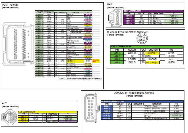
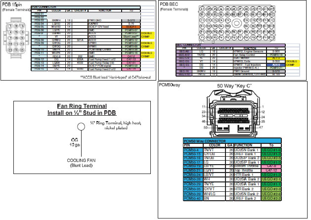
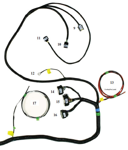
6.0 HARNESS WIRE COLORS AND CONNECTOR LOCATIONS
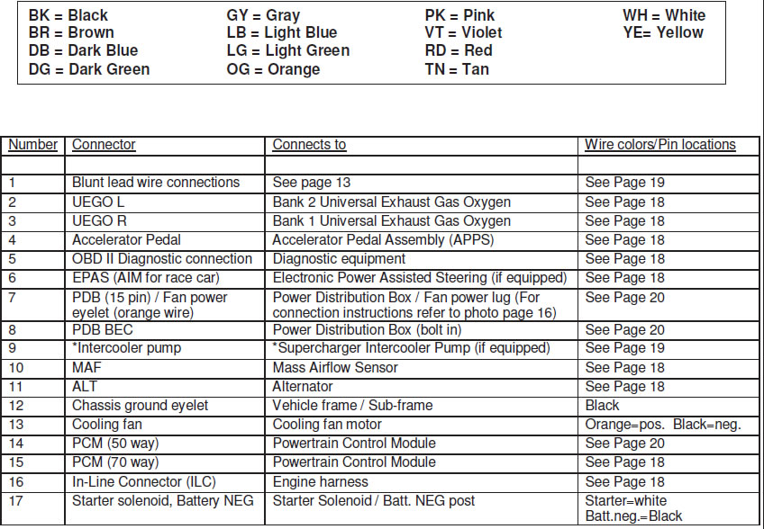
NOTE: Cooling fan is switched on at 195F, turns off at 190F. This is based on inferred engine coolant temperature. Engine coolant temperature is inferred from the cylinder head temperature. Inferred coolant temperature may not be the same as actual coolant temperature.
7.0 HARNESS INSTALLATION
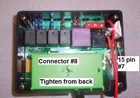
7.1 Attach main harness connector (Connector #8) to the FRPDB. Use a Phillips screwdriver to gently snug the mounting screw for this connector. Access to this screw is through a hole in the back side of PDB.
7.2 Attach the PCM Connector (Connector #15) to the cowl pocket (outside 70 pin connector) of the PCM
7.3 Attach the Auxiliary Inline Connector (Connector #16) to the mating inline connector of a 2011 MY or newer engine harness.
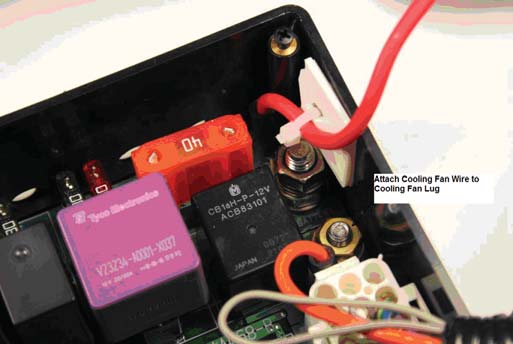
7.4 Attach the 15 pin FRPDB Connector (Connector #7) to the FRPDB. Attach the cooling fan power lead (orange wire with eyelet) to the cooling fan power lug using supplied nut (refer to picture in section 10). Leave the lid off of the FRPDB until verification of installation is complete to allow for trouble-shooting if necessary.
7.5 Using a sheet metal screw, attach the eyelet (Connector #12) to the inner fender or bulkhead. Verify that you have a good reliable ground path from the battery negative post to the location being used for this eyelet on the chassis. In general, the resistance from the battery ground to this chassis location should be less than 0.1 ohm.
7.6 Find a mounting location for the Accelerator Pedal. Ensure that the mounting location is sufficiently strong so the mounting surface will not fatigue over time from the constant usage of the accelerator pedal. If necessary, fabricate an additional support plate for mounting the accelerator pedal. Once the pedal is mounted, attach the Accelerator Pedal Connector (Connector #4)
7.7 Attach the OBD II Diagnostic Connector (Connector #5) at a location of your choosing that will provide easy access for connection of diagnostic tools. This is usually under the dashboard on the driver (left) side of the vehicle. Verify that the connector, once mounted, does not interfere with any part of your body while in the seated position.
Important Note on the Starting System
This kit includes connections and installation instructions for PCM controlled engine starting; however, it is not required that the customer utilize this option. Customers may choose to use their existing non-PCM controlled starting system if desired. If non-PCM controlled starting is used, step 8.2 C may be omitted, and unused blunt leads should be cut to ~2” length and sealed using heat shrink.
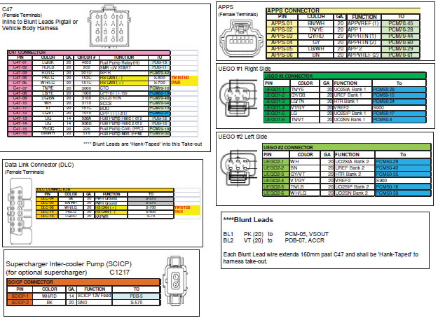
8.0 WIRING CONNECTIONS
8.1 Locate each of the Blunt Leads. This is where you will need to make all of the soldered connections for the harness.
8.2 Connect the blunt leads as follows:
- Blunt Lead 1 – Ignition Switch Position (Red/Light Green Wire): Connect this wire to a SINGLE SOURCE on the ignition switch that provides 12 Volts when the key is in either the ‘Start’ (cranking) or ‘Run’ position. It is imperative that this circuit be reliable, the PCM will interpret an intermittent voltage on this signal as a request to shut down the engine! (Hint, if your engine shuts down after a hard launch check here first).
- Blunt Lead 2 – Fuel Pump (Dark Green): Connect to Fuel Pump positive. Separate ground for fuel pump must be provided. The fuel pump will be running any time key is on.
- Blunt Lead 3 – Starter Motor Request (Red/Light Blue): Connect to start node of ignition switch so that 12 volts is provided when engine starting is requested.*
- Blunt Lead 4 – Clutch Position (Neutral Switch) (Dark Blue/Orange): This circuit must be grounded either directly to ground or through an optional customer provided clutch pedal switch.* (PCM will not engage the starter without proper ground/switch)
- Blunt Lead 5 - CTO (Tan/Yellow): This wire is the tachometer lead. This is not a mandatory connection.* *If non-PCM controlled starting is used, step 8.2 C may be omitted, and unused blunt leads should be cut to ~2” length and sealed using heat shrink.
9.0 Fuel System
The PCM is calibrated for a return style fuel system as shown below.
Notes:
- Set regulator to maintain 55 psi delta fuel pressure across injector (55 psi at fuel rail with engine off):
- Use only AN type fuel fitting to interface with OEM fuel rail.
- Fuel pressure regulator must have reference to manifold vacuum.
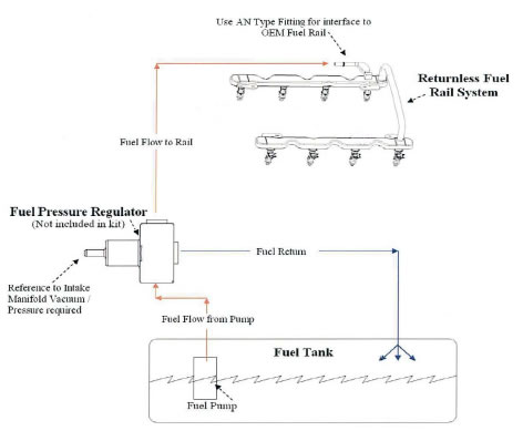
Fuel pump requirements: 155L/Hr minimum at 55psi
Fuel pump location
A common and often overlooked problem is the location of the fuel pump or pumps. Optimally, the fuel pump should be mounted IN THE TANK to reduce the possibility of pump cavitation. Cavitation is essentially localized boiling caused by a reduction in pressure, generally occurring on the inlet side of a pump. This localized boiling results in fuel vapor bubbles which will reduce the volume of fuel the pump is capable of delivering to the engine. Any reduction in pressure or increase in temperature at the inlet side of the pump increases the chances that cavitation will occur. For this reason, it is always best to either have the pump inside the tank immersed in fuel or (in the case of an external pump) gravity fed, which will increase the pressure on the inlet side of the pump. If the fuel pump has to “pull” the fuel, this will result in a reduction in pressure at the fuel pump inlet potentially allowing cavitation and, thus, vapor bubbles to develop. These vapor bubbles are then drawn into the fuel pump and exit the high-pressure side of the fuel pump as compressed vapor.
They travel the entire length of the fuel system and are expelled through the fuel injector. This can cause issues ranging from stumbles and hesitations to engine damage due to insufficient fuel delivery and lean A/F ratios. Sometimes this problem can characterize itself by only appearing when the weather gets warmer, which can confound the diagnosis of the issue. In certain cases, it may seem to only develop when driving on certain surfaces, because pavement reflects more heat than an off-road 4x4 trail. Remember, more heat and lower pressure on the inlet side of the pump means a greater chance of cavitation, which is to be avoided whenever possible.
If you are using an external mounted fuel pump, you should run a very coarse (typically around 100 micron) filter on the inlet side of the fuel pump, and a finer (typically around 10 micron) filter on the outlet side of the pump. A paper filter is NOT recommended on the inlet of the fuel pump because it can cause a restriction in fuel flow which, as mentioned previously, can lead to cavitation.
Warning: It is highly recommended that an inertia switch is incorporated into the fuel pump wiring to turn off the fuel pump in event of an accident.
10.0 FRPDB Installation
10.1 Connect the main power lead from the FRPDB to the battery positive terminal. Note: This lead MUST be hot at all times (HAAT). If this lead is connected through a switch, the Keep Alive Memory (KAM) of the PCM will be cleared whenever the switch is opened. This will result in loss of diagnostic trouble codes, adaptive fuel parameters and other information stored in KAM by the PCM.
10.2 Connect the cooling fan power lead (orange wire with eyelet) to the cooling fan power lug of the FRPDB using supplied nut. Leave the lid off of the FRPDB until verification of installation is complete to allow for troubleshooting.
11.0 INITIAL START UP
The following information assumes completion of each of the previous steps of this installation manual
11.1 Check all fluid levels, electrical and fluid connections.
11.2 Pressurize the fuel system by turning the key on. Inspect the entire fuel system (from tank to engine) for leaks. If any leaks are found, do not proceed further until these have been corrected.
11.3 Start Engine. Check for leaks and/or noises that may indicate a problem.
12.0 CONNECTOR FACES AND WIRE USAGE SCHEMATIc