 FREE 1 to 3-Day Delivery on Orders $149+ Details
How to install a K&N FIPK Cold Air Intake on your 2007-2009 GT Mustang
Installation Time
1 hours
Tools Required
- Flat blade screwdriver
- Ratchet
- Extension
- 10mm socket
- 3.5mm allen
- 4.0mm allen

Shop Parts in this Guide
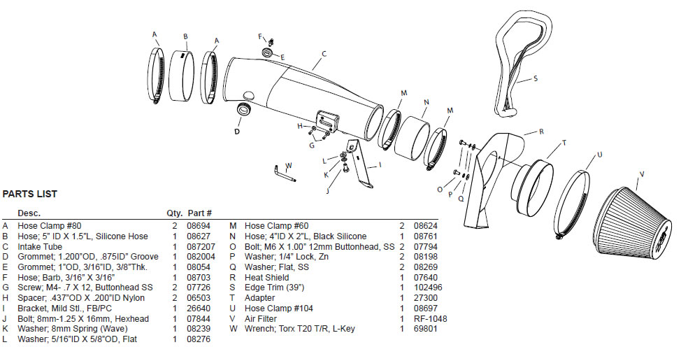
Installation
- Turn off the ignition and disconnect the negative battery cable.
NOTE: Disconnecting the negative battery cable erases pre-programmed electronic memories. Write down all memory settings before disconnecting the negative battery cable. Some radios will require an anti-theft code to be entered after the battery is reconnected. The anti-theft code is typically supplied with your owner’s manual. In the event your vehicles’ anti-theft code cannot be recovered, contact an authorized dealership to obtain your vehicles anti-theft code.
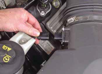
2. Depress the locking tab and then unhook the mass air sensor electrical connection.
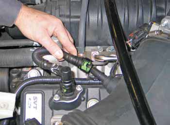
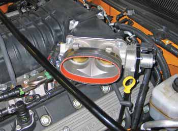
3. Rotate the green locking tab and then disconnect the crankcase vent hose from the intake tube.
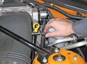
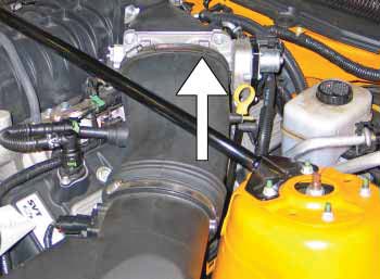
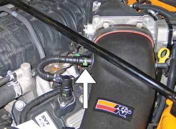
4. Disconnect the vacuum vent line as shown.
5. Loosen the intake hose clamp at throttle body.
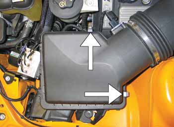
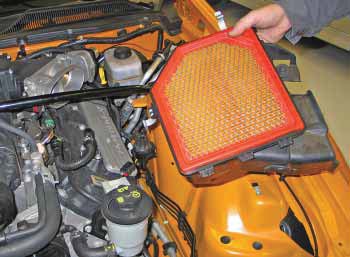
6. Unlatch the two upper airbox retaining clips
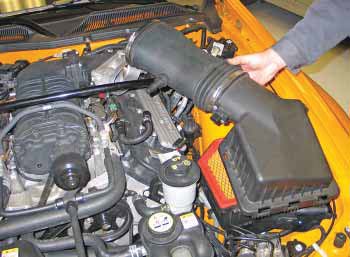
7. Remove the intake tube and airbox lid from the vehicle.
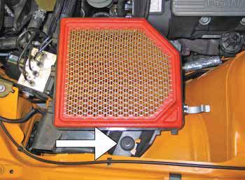
8. Remove the lower airbox retaining bolt shown.
9. Remove the lower airbox housing from the vehicle.
NOTE: K&N Engineering, Inc., recommends that customers do not discard factory air intake.
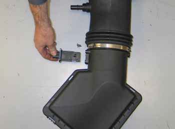
10. Using the provided T20 torx wrench, remove the mass air sensor retaining screws so the mass air sensor can be removed as shown.
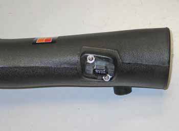
11. Install the mass air sensor into the K&N® intake tube and secure with the provided spacers and m4 bolts.
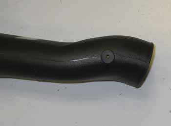
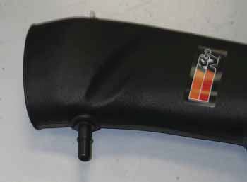
12. Install the supplied ¼”id vent grommet into the K&N® intake tube as shown.
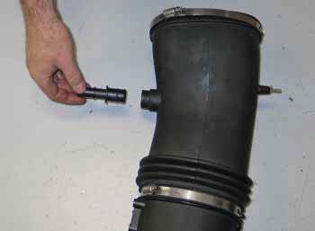
13. Insert the supplied ¼” hose mender into the grommet that was installed in the previous step.
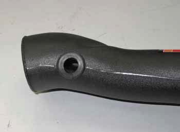
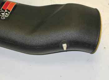
14. Install the supplied crankcase vent grommet into the K&N® intake tube as shown.
15. Cut the clamp securing the crankcase vent fitting into the factory intake tube and then remove the fitting from the intake tube as shown.
16. Install the factory crankcase vent fitting into the grommet installed into the K&N tube in step #14.
17. Install the supplied silicone hose (08627) onto the throttle body and secure with the provided hose clamp.
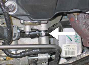
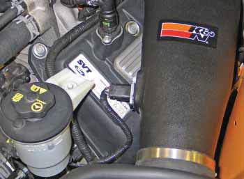
18. Remove the upper alternator mounting bolt shown
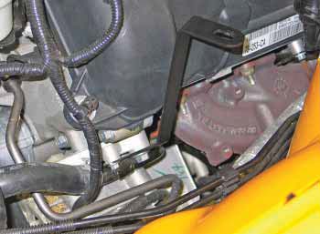
19. Install the tube mounting bracket (08761) onto the alternator bracket with the factory bolt removed in step #18.
20. Install the K&N® intake tube into the throttle body and align with the mounting bracket, then secure with the provided hose clamp and hardware.
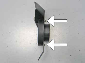
21. Install the filter adapter onto the heat shield using the provided hardware
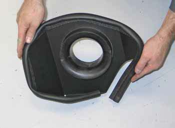
22. Install the edge trim onto the heat shield assembly as shown.
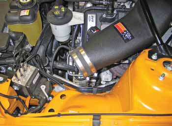
23. Install the silicone hose (08761) onto the intake tube and slide it past the bead on the end of the tube so proper clearance is maintained when the air filter assembly is installed.
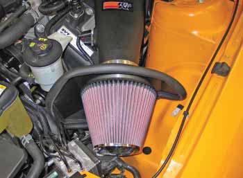
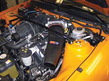
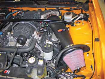
24. Set the filter assembly into the position. Slide the silicone hose onto the filter adapter’s inlet and and secure the filter assembly to the intake tube with the provided hose clamps.
25. Connect the vacuum vent line onto the ¼” hose mender that was inserted in the K&N® intake tube during step #13.
26. Attach the crankcase vent hose to the factory fitting that was installed in the K&N® intake tube in step #15.
27. Reconnect the mass air sensor electrical connection.
28. Reconnect the vehicle’s negative battery cable. Double check to make sure everything is tight and properly positioned before starting the vehicle.
29. The C.A.R.B. exemption sticker, (attached), must be visible under the hood so that an emissions inspector can see it when the vehicle is required to be tested for emissions. California requires testing every two years, other states may vary.
30. It will be necessary for all K&N® high flow intake systems to be checked periodically for realignment, clearance and tightening of all connections. Failure to follow the above instructions or proper maintenance may void warranty.
ROAD TESTING:
1. Start the engine with the transmission in neutral or park, and the parking brake engaged. Listen for air leaks or odd noises. For air leaks secure hoses and connections. For odd noises, find cause and repair before proceeding. This kit will function identically to the factory system except for being louder and much more responsive.
2. Test drive the vehicle. Listen for odd noises or rattles and fix as necessary.
3. If road test is fine, you can now enjoy the added power and performance from your kit.
4. K&N Engineering, Inc., suggests checking the air filter element periodically for excessive dirt buildup. When the element becomes covered in dirt (or once a year), service it according to the instructions on the Recharger® service kit, part number 99-5050 or 99-5000.

