 FREE 1 to 3-Day Delivery on Orders $149+ Details
Mustang Clear Lens Instrument Cover ('90-93) - Installation Instructions
Installation Time
30 minutes
Tools Required
- Phillips Screwdriver
- 5/16" Socket or 8mm Hex
- T20 Torx or 7mm Hex
- T15 Torx or 6mm Hex
- Sizeable Flat Blade Screwdriver
- Compressed Air Bottle
- "Swiffer-Type" Dusting Cloth
- Anti-Static Camera Lens Brush or Very Soft Brush
Shop Parts in this Guide
Installation
1. Prep the car. Park on a level spot, set the hand brake and take the keys out of the ignition. Park on a level spot, set the hand brake and take the keys out of the ignition. Clean the dash area to help prevent dirt and debris from falling onto your gauges when exposed.
2. A dusty dash and scratched lens. Daytime gauge visibility was poor due to glare across lens. At night the gauges appeared “foggy” and out of focus.
3. This is the two piece (top / bottom) plastic cover that surrounds the ignition switch on one side and the turn signal lever on the other. It is held in place by two Phillips head screws which are accessed from underneath. (See Fig.1) Remove the screws and carefully unsnap the two halves, put the screws in the cup for later use.
4. Remove the knee-guard cover and metal knee-guard. Some Mustangs were equipped with a more streamlined, less bulbous version of this knee-guard but the removal is basically the same. Remove the three 5/16” (8mm) hex bolts along the bottom edge of the knee-guard, putting all the fasteners/ washers in the cup. NOTE: It is unnecessary to remove the bolts holding the hood release lever or the screw holding the trim at the end of the dash. (See Fig.2)
Fig. 2
5. With the lower edge screws out, you can now pull the top of the cosmetic cover free with a moderate tug from around the edges; it is secured at the upper corners by snap through connectors. Set this cover aside in a safe place for reinstallation later. (See Fig.3)
Fig. 3
6. Now visible and can be freed by removing the two remaining 5/16” (8mm) bolts on either side of the steering column. Also, remove the bolt that attaches the pod support brace just above the knee-guard on the right side upper edge. (See Fig.4)
Fig. 4
7. Remove the headlight / fog-light and hazard / convertible top switch assemblies from the dash pod- On either side of the instrument pod there are switches that must be removed before the dash pod can come off. These switch assemblies are held in place by plastic tabs along their sides. Gently depress the tabs while pulling the switch toward the steering wheel, this should release one side of the assembly allowing you to free the other side and pull the switch a. few inches from the pod. Repeat this procedure for both switch assemblies. (See Figs.5 and 6) ***NOTE: There is a high probability that the small plastic tabs on these are brittle due to age, use caution when removing.
8. Unplug the wiring harness - Gently pry the locking clips up while pulling the harness connector off the back of the switch; repeat this for the other side as well. (See Figs 7 and 8). ***Again, care is required to prevent damage to these small clips, tabs and connectors. I used a small flat blade screw driver to assist with both the pressing and prying of tabs during this step.
Fig. 5
Fig. 6
Fig. 7
Fig. 8
9. Separate the instrument pod (hood) from the rest of the dashboard- There are two screws located on the top of the pod near the base of the windshield. I used a T20 torx bit and a small ‘gear-wrench’ to remove these due to the tight space between them and the windshield. (See Fig.9) The instrument pod hood can be removed by pulling toward the steering wheel, up and away; the lower edge may need some coaxing to free it from around the dash lights dimmer wheel. (See Fig.10)
Fig. 9
Fig. 10
Fig. 11
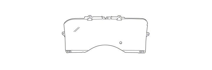
10. Remove the clear instrument lens- At this point you can remove the six small T15 torx (6mm) hex screws from around the perimeter of the clear instrument lens, gently pull the lens from the edges to reveal the gauges and bezel. (See Fig.11)
Fig. 12
11. Clean the gauge area and install the new clear lens.
NOTE:I decided to remove instrument assembly from the car completely (for more detailing and better illustrative purposes) but the lens can be replaced with the instruments in the car, without disconnecting any gauges.
12. I cleaned the gauge faces and bezel area using some canned air and a very soft brush. (See Fig.12) REMEMBER: DO NOT USE ANY LIQUIDS TO CLEAN THE GUAGES/INSTRUMENT PANEL or DAMAGE WILL OCCUR!
13. The new lens arrived in a cardboard package, protective wrap, sparkling clean and crystal clear! It should be handled by the edges to avoid getting any finger-prints or other particles on the lens. (See Fig.13)
14. I then removed the new lens from the packaging, matched up the alignment pins and put the small screws in with a couple of turns by hand on each. (See Figs.14 and 15)
15. Now is a good time to clean off all the pieces of the dash that were removed so far. I used a little mild soap & warm water to wipe down the plastic, allowing for time for things to dry completely before putting it all back together.
Fig. 13
Fig. 14
Fig. 15
16. Reassemble the instrument pod- Tighten the lens screws until all six are finger tight and just ‘snug’ (do not over-tighten these little screws!).
17. Fit the pod (hood) back into its original position over the gauge cluster and install the screws finger tight at the top (near the wind shield) first. Put the pod brace bolt (from step 3) in place at the lower edge of the pod, then snug down all three screws just tight enough so that things won’t rattle.
18. Route the wiring harnesses through the openings in the pod sides; reconnect the switch assemblies by snapping the connectors on securely. Gently push the switches into the pod until they click into their original positions. Check all of the switch functions for normal operation and correct as needed before proceeding.
19. Reinstall the knee-guard and cover- Hold the metal knee-guard in place over the plastic mounting tabs of the pod, insert the two upper bolts (from Fig. 4) and screw down until only finger tight. Visually double check the alignment of the lower edge bolts (from Fig.2), and if aligned, then tighten the two upper bolts to factory torque specs.
20. The cosmetic cover can be snapped in place at the upper corners and both the metal and plastic panels can be re-attached along the bottom edge again using the three original bolts.
21. Replace the steering column covers- Snap the halves of the cover together and install the screws from underneath, as seen in Fig.1. Congratulations, the installation is complete. Seat adjustment may be required before driving.
Fig. 16
22. The impact of this simple change is amazing. From the driver’s seat the instrument visibility is perfect, like a new car. The gauges are far easier to read, especially at night, which improves the driving experience overall. For only a few hours invested, the payoff is great! I strongly recommend this inexpensive project to anyone who has a Mustang that they intend to keep and drive as often as I do.
Installation instructions provided by Curtis Calfee 1.2.10
Related Guides
-
Installation
-
Installation
-
Installation

