FREE 1 to 3-Day Delivery on Orders $119+ Details
Best Sellers


How to install Maximum Motorsports Caster Camber Plates on your 2005-2009 Mustang
Shop Parts in this Guide
Installation
Maximum Motorsports continues our tradition of designing and manufacturing the finest doubleadjustable Caster/Camber Plates with th is version for the latest generation Mustang. Offering the same great functionality that our Caster/Camber Plates have long been famous for, Maximum Motorsports has once again set an industry standard!
A must for any lowered S197 Mustang, the MM Caster/Camber Plates have separate adjustments for both camber and caster, and provide the largest continuous range of alignment settings possible. This allows correction of the excessive negative camber caused by lowering. Even a Mustang lowered as much as 2.5 inches can still be aligned to factory specifications.
- 1.6-degree continuous range of camber adjustment provides alignment correction on lowered cars, and is adjustable without affecting caster.
- 0. 7 -degree continuous range of caster adjustment provides correction for OEM production tolerances.
- Caster and camber are easily adjusted at the top of the strut tower.
- The range of suspension travel can be shifted, allowing for additional bump travel on lowered cars.
- Teflon® lined spherical bearing eliminates deflection and precisely locates the strut shaft, while still allowing the required articulation.
- High-tech composite thrust bearing transfers the spring load into the strut tower.
- All parts are either plated or powder coated for great looks and long lasting protection.
- Lifetime warranty against spherical bearing or plate failure.
Read all instructions before beginning work. Following instructions in the proper sequence will ensure the best and easiest installation. NOTE: We highly recommend replacing the strut-tospindle mounting hardware while installing this kit. Ford considers this hardware to be one-time use only. The new OEM hardware can be purchased from your local Ford dealer or Maximum Motorsports (part# MMF-3). Four (4) bolts W714652 5439 and four (4) nuts W714653 5900 are required. Note that this is newly updated Ford hardware; it is now fine-thread, and requires a higher tightening torque. The new torque specification for this hardware is 166 lb-ft.
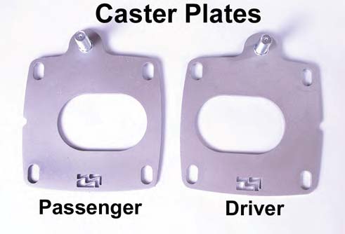
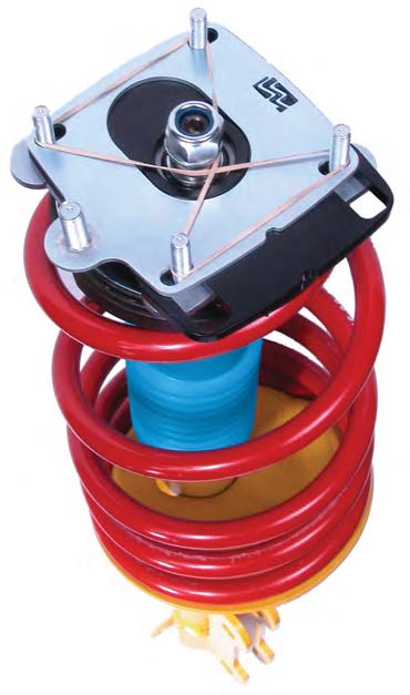
Caster/Camber Plate Assembly
1. Remove the packaging material from the Maximum Motorsports Caster/Camber Plates and arrange the components as depicted below.
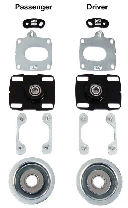
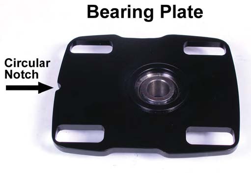
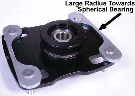
NOTE: The Bearing Plates are not side specific, but they must be correctly oriented during installation in order to properly function. For correct orientation, the circular notch on the Bearing Plate must face towards the outboard side of the vehicle and the spherical bearing must be below the Bearing Plate.
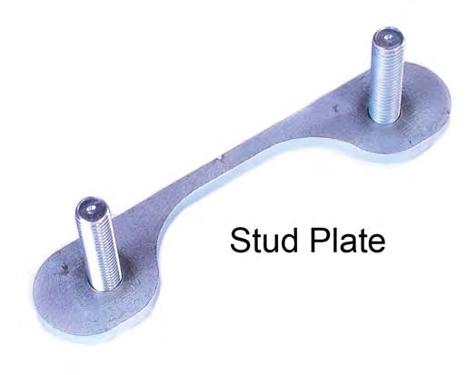
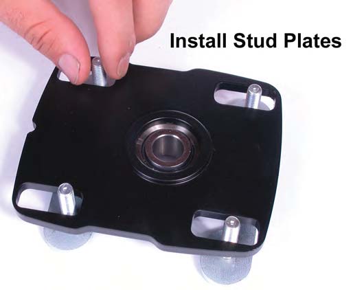
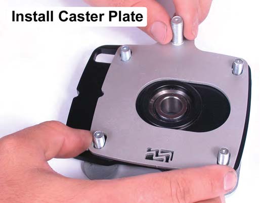
2. Starting with the passenger side Bearing Plate, install two of the provided Stud Plates from the bottom of the Bearing Plate, with the studs protruding up through the slots of the Bearing Plate. Position the two Stud Plates so that the large radius, located between the two studs of each Stud Plate, faces the spherical bearing.
3. Place the passenger side Caster Plate on top of the passenger side Bearing Plate, making sure that the raised lip around the spherical bearing protrudes up through the center slot of the passenger side Caster Plate. The Caster Plate notch should be aligned with the Bearing Plate notch, and both are oriented towards the outboard side of the car.
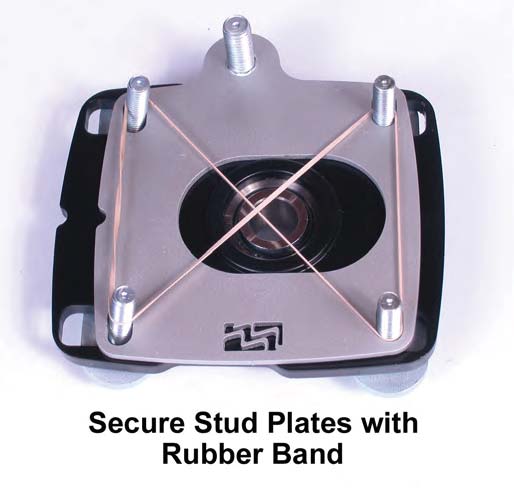
4. Take one of the supplied rubber bands and wrap it around the studs as shown. The purpose of this rubber band is to hold the Stud Plates in position while installing the MM Caster/Camber Plates.
5. Repeat Steps 2-4 for the driver side.
Strut Removal Procedure
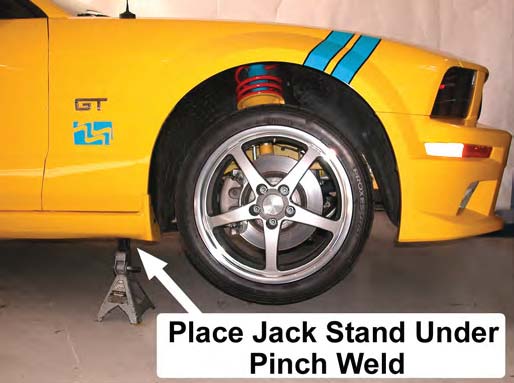
6. Place the front of the car safely on jack stands, or on a lift.
7. Remove the front wheels.
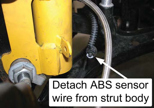
8. Starting on the passenger side, disconnect the brake line bracket and the ABS sensor wire from the strut.
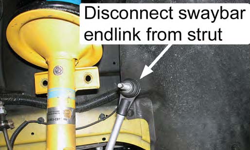
9. Disconnect the swaybar endlink from the strut.
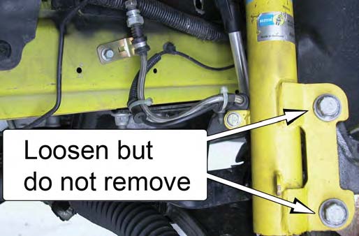
10. Loosen, but do not remove, the strut-to-spindle mounting bolts.
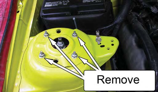
11. Remove the 4 upper strut mount nuts, located on top of the strut tower.
12. Remove the lower strut-to-spindle mounting bolts, and then remove the strut/spring assembly from the vehicle.
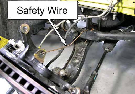
NOTE: Use a metal hanger or safety wire to prevent the spindle from placing a strain on the brake lines.
Strut Mount Swap Procedure
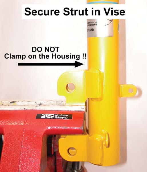
If possible, secure the strut in a vise before continuing. This will provide for an easier installation. Do not clamp down on the strut housing, as damage to the internal components will occur.
NOTE: Be careful not to clamp on the strut mounting ears so hard as to bend them together.
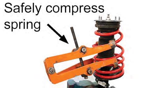
13. Using an external spring compressor, compress the spring to release the spring force on the upper strut mount assembly.
NOTE: The spring is under considerable pre-load. You MUST secure the spring with an external spring compressor before attempting to disassemble the spring from the strut. Not following the proper disassembly procedure may cause severe personal injury and property damage.
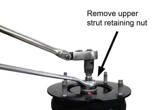
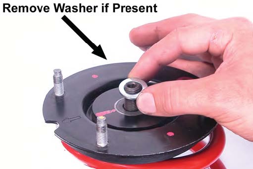
14. Remove the upper strut-retaining nut, and washer if present.
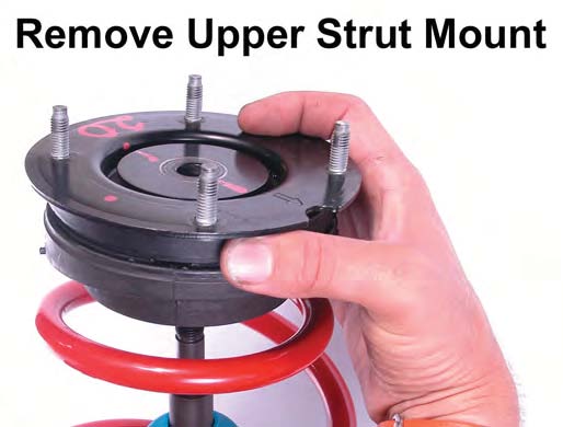
15. Remove the upper strut mount assembly from the strut shaft.
NOTE: Spring compressor removed for clarity.
16. If retaining the currently installed springs, skip to Step 18. If changing the spring, uncompress the spring and remove the spring compressor from the spring. Then remove the spring from the strut.
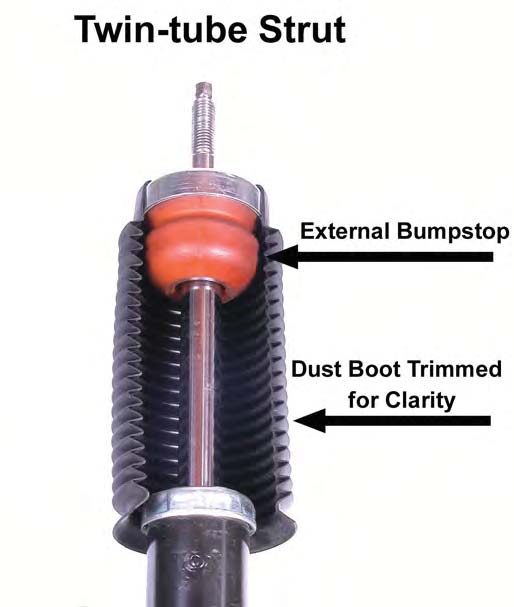
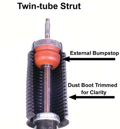
NOTE: All Twin-tube struts feature an external bumpstop that is located on the strut shaft. This bumpstop must be used.
17. Install the replacement spring onto the strut. Compress the spring with the spring compressor enough to install the MM Caster/Camber Plate assembly shown in Step 22.
18. Use a flat screwdriver to pry the stock upper rubber isolator from the upper strut mount assembly.
NOTE: Retain the rubber isolator, as it will be reused with the MM Caster/Camber Plates.
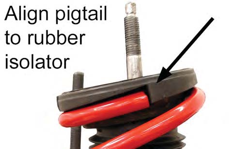
19. Place the stock upper rubber isolator onto the top of the spring.
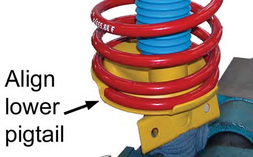
NOTE: Make sure to correctly align the top "pigtail" of the spring with the vertical face on the stock rubber isolator, and the bottom "pigtail" of the spring with the vertical face on the lower spring perch.
NOTE: Spring compressor removed for clarity.
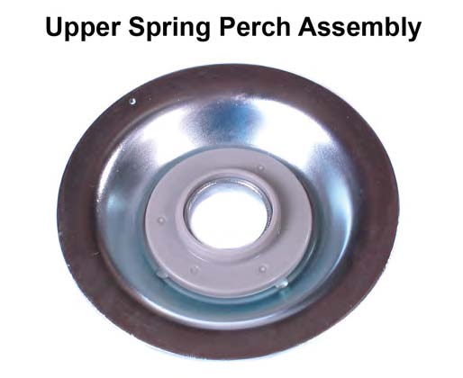
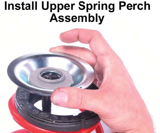
20. Place the MM Upper Spring Perch Assembly on to the top of the stock upper rubber isolator. The strut shaft will protrude through the center hole of the spring perch.
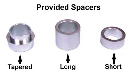
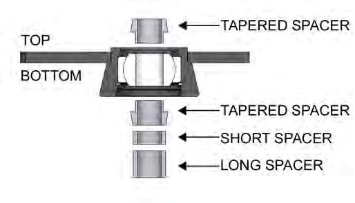
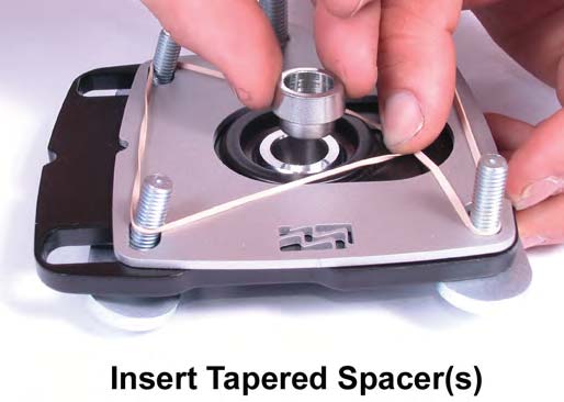
21. Place the spacer stack configuration shown below onto the strut shaft and into the spherical bearing. Ensure that the tapered spacers are properly seated against the shoulder of the spherical bearing.
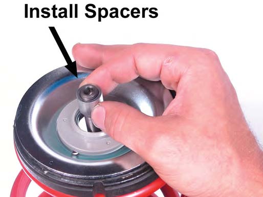
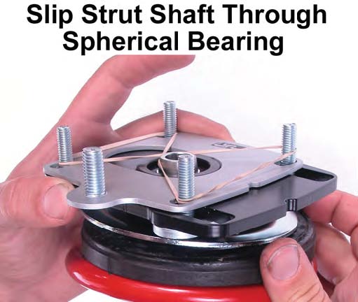
22. Place the passenger side MM Caster/Camber Plate assembly onto the strut shaft by slipping the shaft through the spherical bearing. Take care not to dislodge either of the tapered spacers from the spherical bearing.
23. Reinstall the upper strut retaining nut, and washer if used, and torque to the manufacturer's recommended value. If using OEM or Tokico struts, torque to 45 lb-ft. If using Bilstein or H&R struts, torque to 54 lb-ft.
24. Slowly release the spring tension and remove the spring compressor from the strut. While loosening the spring compressor, make sure that both pigtails are properly located both in the lower spring perch and on the upper rubber isolator.
The strut & spring assembly is now ready to install in the car.
Strut Reinstall Procedure
23. Reinstall the upper strut retaining nut, and washer if used, and torque to the manufacturer's recommended value. If using OEM or Tokico struts, torque to 45 lb-ft. If using Bilstein or H&R struts, torque to 54 lb-ft.
24. Slowly release the spring tension and remove the spring compressor from the strut. While loosening the spring compressor, make sure that both pigtails are properly located both in the lower spring perch and on the upper rubber isolator.
The strut & spring assembly is now ready to install in the car.
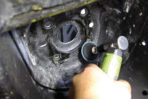
25. Check the bottom of the strut tower for any raised metal flashing . You should be able to run your fingers across the surface without catching them on anything. File or sand down any roughness detected.
NOTE: The bottom of the strut tower must be smooth to allow the MM Caster/Camber Plate to slide freely during the alignment procedure.
NOTE: Do not tighten the MM Caster/Camber Plate mounting nuts until instructed to do so. Thread the nuts on by hand until the tip of the bolts touch the Nylock portion of the nut.
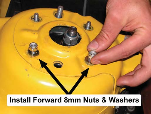
26. Reinstall the strut assembly into the vehicle. Be careful to orient the notches on the MM Caster/ Camber Plate towards the outboard side of the vehicle. Install the forward 8mm nuts and washers to hold the assembly in place and thread them on until the tip of the bolts touch the Nylock portion of the nut.
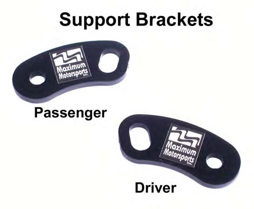
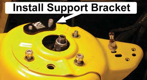
27. Place the passenger side Support Bracket onto the protruding studs, as shown in the photo. The Support Bracket should be oriented towards the outboard side of the vehicle.
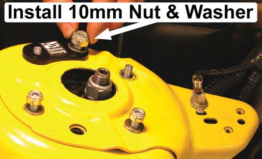
28. Place one of the provided large G8 washers on to the Caster Plate Stud, followed by one of the provided 1 Omm Nylock nuts and thread it on until the tip of the bolt touches the Nylock portion of the nut.
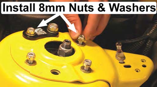
29. Place one of the provided small G8 washers onto each of the remaining studs, followed by the provided 8mm Nylock nuts, and thread them on until the tip of the bolt touches the Nylock portion of the nut.
30. Reach through the hole in the top of the strut tower, and pull on the rubber band attached in Step 4 until it breaks. Completely remove the rubber band. Snug all five nuts on the MM Caster/Camber Plate.
31. Reattach the strut to the spindle and torque the lower mounting bolts to 166 lb-ft.
NOTE: To ensure your safety, all S197 Mustangs should have the strut to spindle mounting hardware replaced with the latest OEM revision. Ford has switch to fine-thread fasteners because they provide a higher clamp load on the spindle to strut mount.
This OEM hardware can also be purchased from Maximum Motorsports.
32. Reattach the brake line bracket and the ABS sensor wire removed in Step 8.
33. Reattach the swaybar endlink to the strut and torque the mounting nut to 85 lb-ft.
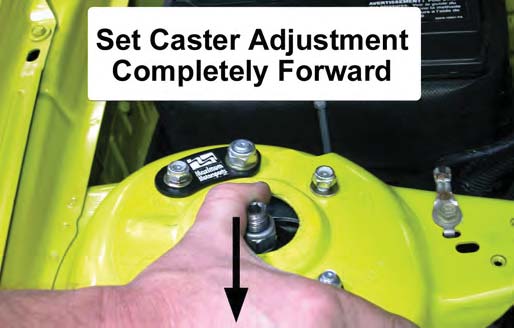
34. Loosen the five nuts on the MM Caster/Camber Plate very slightly, until the plate can barely slide in its adjustment slots. Slide the entire MM Caster/Camber Plate assembly forward and torque the 1 Omm nut to 26 lb-ft.
NOTE: It is easiest to grab on to the strut housing from underneath the fender and pull it forward.
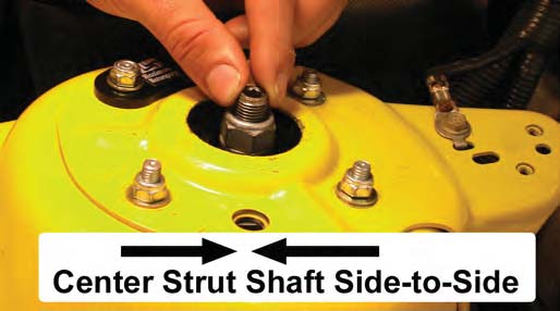
35. Next, center the strut shaft in the strut tower opening side to side. Once centered, torque the four 8mm Nylock nuts to 20 lb-ft.
NOTE: It is easiest to grab on to the strut housing from underneath the fender, and push/pull it inboard or outboard.
36. Repeat Steps 8-35 for the driver side of the vehicle.
37. Reinstall the wheels and safely lower the vehicle to the ground. Torque the lug nuts to the manufacturer's specifications.
38. The car must now have a proper front-end alignment. While some do-it-yourselfers perform their own alignments at home with the help of a Maximum Motorsports Camber Gauge, many people elect to take their Mustang to a professional alignment shop. On the following page is important information to pass on to the alignment technician.
Important Notes for Alignment
- 4The Caster/Camber Plate will NOT move if the front suspension is loaded. The front end MUST be raised. BOTH front wheels must be off of the ground in order to adjust the caster and camber. You cannot simply jack up one side of the vehicle to adjust the alignment, because the front sway bar will transmit a load to the raised side, from the other side's suspension.
- While caster and camber are adjusted separately with the MM plates, the caster should be adjusted first, locked down, and then the camber adjusted.
Alignment Recommendations
Caster
It is typical for alignment shops to set the passenger side caster to a slightly greater amount than the driver side setting. For street-driven cars, a difference of 1/4° to 1/2° will help counter the effect of road crown, and prevent the car from pulling towards the right on most roads.
Unlike camber, there are many variables that affect the caster. For example, if the car has any rake, the measured amount of caster will be less than if the car was level. Changes in ride height will affect the measured amount of caster. Different technicians using different alignment equipment will measure caster at varying amounts. Unlike camber, the number of degrees that caster is set to does not have to be exact. As long as caster is in the desired range, and the difference from one side to the other is not greater than 1/2°, it is acceptable.
Camber
On the other hand, camber should be set very carefully.
- Street-driven cars: 1° negative, /-1/4°. Keep a close watch on tire wear patterns, and adjust camber to reduce poor wear, if necessary.
- Race cars: Depends greatly upon the track, driver, etc. Usually set around 2° negative as a starting point. Adjustments should be made after checking tire temperatures and wear patterns.
Toe setting
- Street-driven cars should be set at toe-in for straight-line stability. They can be set to the factory specification of 0.5° toe-in.
- Competition cars are typically set up with some amount of toe-out, for quicker turn-in response and increased front grip. A typical starting point would be 0.5° toe-out.
Remember that any time any change is made to the camber setting, the toe setting will be affected, and must be readjusted. It is a good idea to always keep a record of the alignment settings. Inspect the tires frequently for uneven tread wear patterns. If uneven tire wear becomes evident, have the alignment adjusted. With a record of the previous alignment it will be easier to diagnose the problem and make alignment adjustments to improve tire wear.
Maximizing Bump Travel
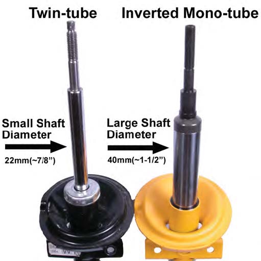
The MM Caster/Camber Plates allow the bump travel range of the strut to be changed from stock Moving the strut shaft upwards shifts the range of travel up, which can restore the bump travel lost when the car was lowered. How much it can be moved depends on the style of strut used. There are currently two styles of struts available for the 2005 Mustang, an inverted mono-tube style and a twin-tube style.
The inverted mono-tube struts can be identified by its larger diameter strut shaft. The following diagrams show the recommended initial spacer stacks for the two styles of struts.
Please note that these recommendations only rovide a starting point for the fine-tuning of an advanced installation. It is common for interference to occur between the top of the strut and the underside of the hood. When positioning the strut shaft with one of the arrangements shown, carefully lower the hood to check for interference.