 FREE 1 to 3-Day Delivery on Orders $149+ Details
How to Install an MSD Launch Master 2-Step Rev Limiter on a 2011-2012 Mustang GT
Shop Parts in this Guide
Installation
Parts Included:
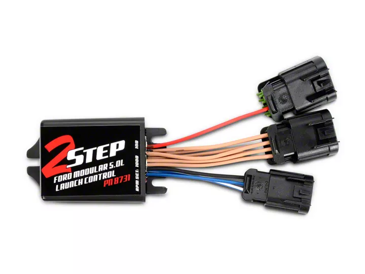
- 1 - 2-Step Launch Control
- 1 - Harness
Parts Bag:
- 1 - Tap
- 3 - Mounting Screws
The 2-Step Launch Control is a low rpm limiter only. The factory speed limiter will not be affected.
This MSD 2-Step Launch Control is designed for Ford Modular 5.0L engines with Coil-on-Plug ignitions. The 2-Step Control switches to a lower rpm limit that will assist in consistent launches and 60-foot times. RPM adjustments are made via two rotary switches located on the harness side of the unit. The adjustment range is from 1,000 - 10,900 rpm, in 100 rpm increments. An LED will illuminate when the launch rev limit is active.
Note:It is recommended to have the Service Manual for your vehicle. If you cannot identify an activation wire, a microswitch or relay may be required.
Note:The engine rpm must drop more than one third of the set launch limit in order to activate. For example, if the launch limit is set at 3,000 rpm, the engine speed must drop below 2,000 rpm in order for the launch limit to become active (one third of 3,000 rpm is a 1,000 rpm drop).
Caution:Keeping the engine on a lower rpm limit may cause the Check Engine light to come on and could potentially damage the catalytic converter.
IMPORTANT:Due to wiring variations on different models, MSD cannot identify specific wiring on the clutch switches. Consult your Service Manual for wiring schematics.
MOUNTING
The 2-Step Control can be mounted in any position but keep in mind to mount it so the rotary dials are accessible for adjustments. Hardware is supplied for mounting. Before mounting the unit, confirm that the wiring harnesses reach their connections.
| WIRING | |
| 8-WIRE CONNECTOR | |
| Tan (8) | Signal Connections. |
| 8-WIRE CONNECTOR | |
| Red | 12 volt Connection through this single Red wire. |
| 3-WIRE CONNECTOR | |
| Black | Connects to a good engine round or the negative battery terminal. |
| Blue | Activation Wire. When grounded, the launch feature will be active. |
| White/Blue | Activation Wire. When switched to 12 volts, the launch feature will be active. |
1. Connect the 3-pin harness to the 2-step and connect the Black wire to the good engine or chassis ground.
2. Disconnect the 2-pin connectors from each of the eight ignition coils.
3. Connect all eight of the 2-pin male connectors from the MSD harness into the factory coil connectors.
4. Plug the 8-pin connector with the single Red wire from the 2-Step to the connector with Black wires.
5. Turn the key to the On position - do NOT start the engine. Look at the LED on the 2-Step:
LED On - This confirms that the wiring is correct and you can move to step 6 (Figure 1).
LED Off - The wiring is different for this application and needs to be changed. Turn the key Off, plug the8-pin connector with the eight Gray wires into the connector with the single Red wire (Figure 2).
6. Connect the 8-pin harness with the tan wires to the remaining connector on the harness.
7. Connect all eight of the female 2-pin connectors from the MSD harness into the factory coils.
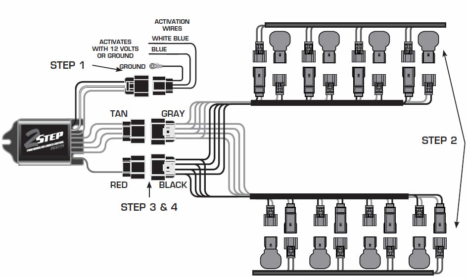
Figure 1 Wiring the 2-Step Launch Control.
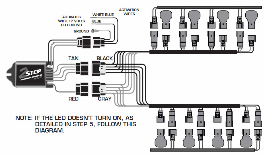
Figure 2 Alternate Wiring.
CONNECT THE ACTIVATION WIRE
The launch rpm limit can be activated through a ground or a 12 volt source.
Ground:Switch the Blue wire to ground to activate the launch limit.
12 volts:Connect the White/Blue wire to 12 volts to activate the launch limit.
If you are planning to use the factory clutch switch to activate the 2-Step, note that there may be variations in factory wiring colors and outputs. It is recommended that you have the factory wiring diagram and schematic. Also, check any wiring for voltage or ground with the key on, during cranking and when the engine is running. A relay may be required with factory wiring systems.
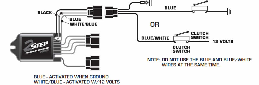
Figure 3 Wiring the Launch Activation Wire.
CONFIRM INSTALLATION
With the power On, engine running, activate the On/Off switch. If connected correct, the LED will illuminate when the clutch is activated. To verify the rpm, set the limit at a lower rpm, such as 2,000, and test the system.
If the engine has trouble starting or running. check the following:
- Ground or switched 12 volts connection
- Coil connections
- The two 8-pin connectors may be in the wrong position and should be swapped and tested again.

