 FREE 1 to 3-Day Delivery on Orders $149+ Details
How to install an MSD Programmable Digital Shift Light on your Mustang
Installation Time
2 hours
Tools Required
- MSD Shift light with all supplied pieces:Shift Light, Mounting Bracket, GMR Pickup, Washers, Screw & Parts BagP1 Phillips Screwdriver (the small one)
- Flathead Screwdriver
- Metal Coat Hanger (to pull cable through the fire wall)
- T-20 Torx Tool
- Assorted Electrical Connectors or Solder Gun, Solder, Electrical Tape
Shop Parts in this Guide
Installation
Overview:The purpose of this write up is to aid in the installation of the MSD Digital Programmable Shift Light for Mustangs. The specific steps for instillation provided are for the 96-04 Mustang, although the general process can be applied to any Mustang.
Installation Instructions:
Step 1:Before starting the install, be sure to disconnect the battery at the negative terminal for safety. It is not a great idea to be working with hot wires while the battery is still connected.
Step 2:Begin by locating the GMR Pickup cable supplied with the shift light. The end of the cable must be routed into the inside of the vehicle. To accomplish this, I found the easiest way is to cut a coat hanger, fasten the cable to it, and use the coat hanger to pull the cable through the grommet in the firewall and into the vehicle.
The grommet is located close to the master cylinder and can also be seen from the inside of the car underneath the dash by the clutch pedal assembly. This is the most frustrating part of installation. I found that lubricating the wire and coat hanger saved time, but this part will take some patience and ingenuity.
Step 3:Once the GMR cable is through the firewall, the next step is to remove the plastic trim piece around the gauge cluster.
It is held in by two T-20 torx bolts and the fog light knob. Remove the bolts that go through the top of the trim piece. To remove the fog light knob pull it out and spin it counter-clockwise until a slit is visible and facing the driver’s side door. There is a small clip inside holding it on that is now accessible. Use a small screw driver or Alan key to lift the clip towards the driver’s side door. Now the knob can be pulled off using some force. It is very easy to break the clip. Now simply pull the trim piece outwards and set aside.
Step 4:Next comes the removal of the gauge cluster.
It is held into the dash by (4) T-20 torx bolts, which need to be removed. Now only (2) electrical connectors on the back of the cluster are holding it in place.
Slide the cluster forward just enough to get your hand around to the connectors. There is a white connector and a black one. Push the tabs in the middle of the connectors and remove cluster.
Step 5:With the cluster out of the way, the GMR cable can be pulled up through the dash. There are many channels behind the cluster that can be used. The coat hanger is again helpful here.
Now, it’s time to wire.
Step 6:Connect the green, red, and black wires from the GMR cable to the corresponding green, red, and black wires coming off the back of the shift light making it one cable.
Step 7:Now connect the green wire with a 12v switched source and the black wire to a ground. I found that splicing into the rear window defog switch is the easiest. It is close in proximity and fused, but any 12v “key on” source and ground will do.
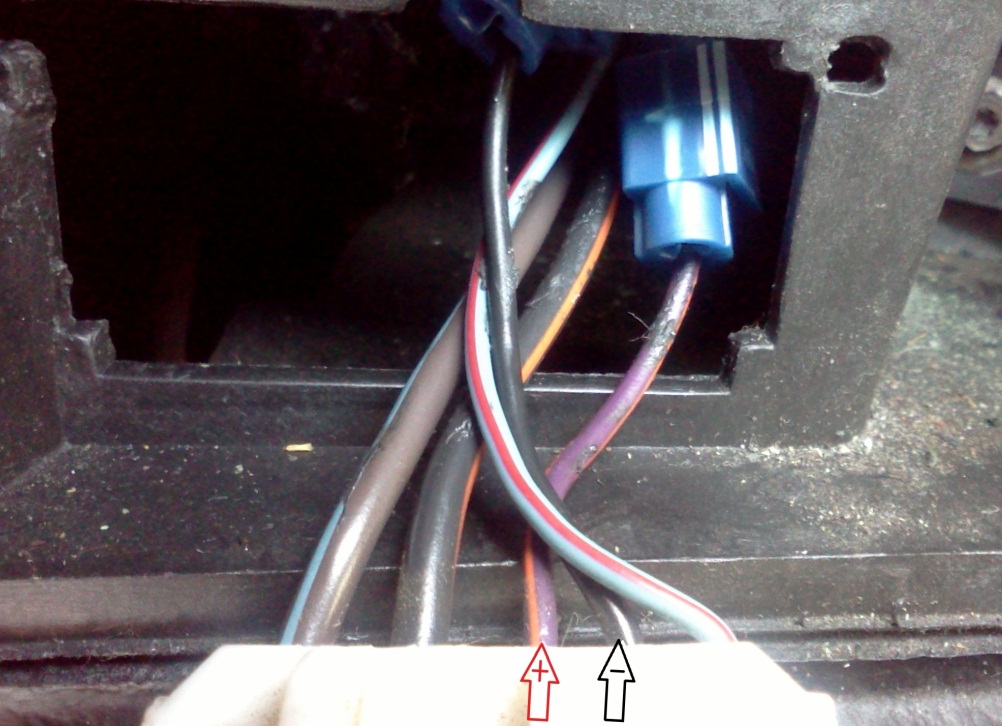
- To connect to Defog Switch (optional): Pull out the rear window defog button by pressing in the two silver tabs on either side of the face and pulling the switch towards the rear of the car. One tab is easy to reach and the other requires use of a flat head screwdriver to depress it.
- Look at the back of the defog switch. There are (5) wires going into (5) different slots. The first slot should be a brown/light blue wire, the second a black/orange wire, the third a purple/orange, the fourth a black wire, and the fifth a light blue/red. Connect the green wire from the MSD shift light to the purple/orange wire in the third slot of the switch. This is a 12v switched source. Connect the black wire from the shift light to the black wire in the number four slot of the switch. This is a ground wire.
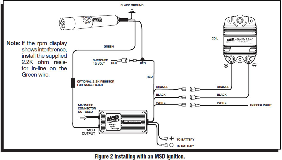
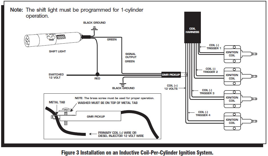
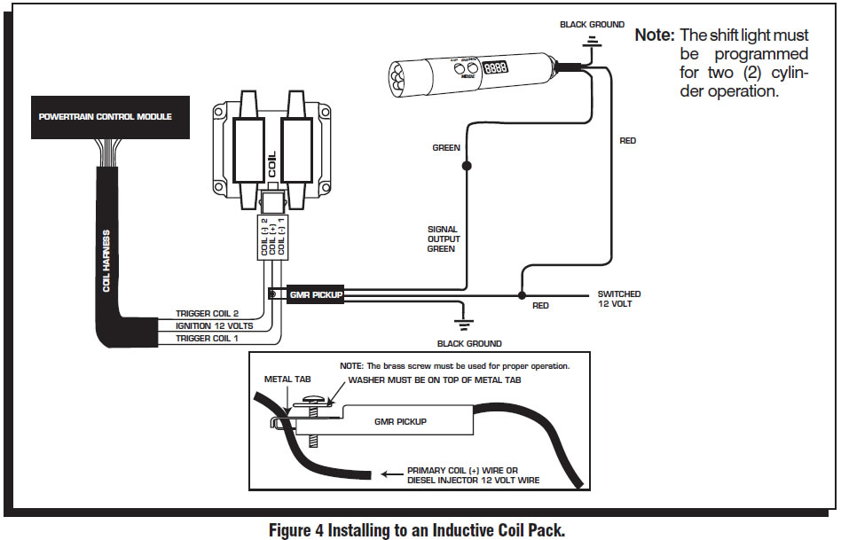
Step 8:Complete the installation by going back to the engine bay and connecting the GMR pickup to a primary coil ( ) wire. On mustangs with coil packs, use the red wire going into the electrical connector on either coil. With coil-on plug applications, connect to the red wire going into any of the ignition coils.
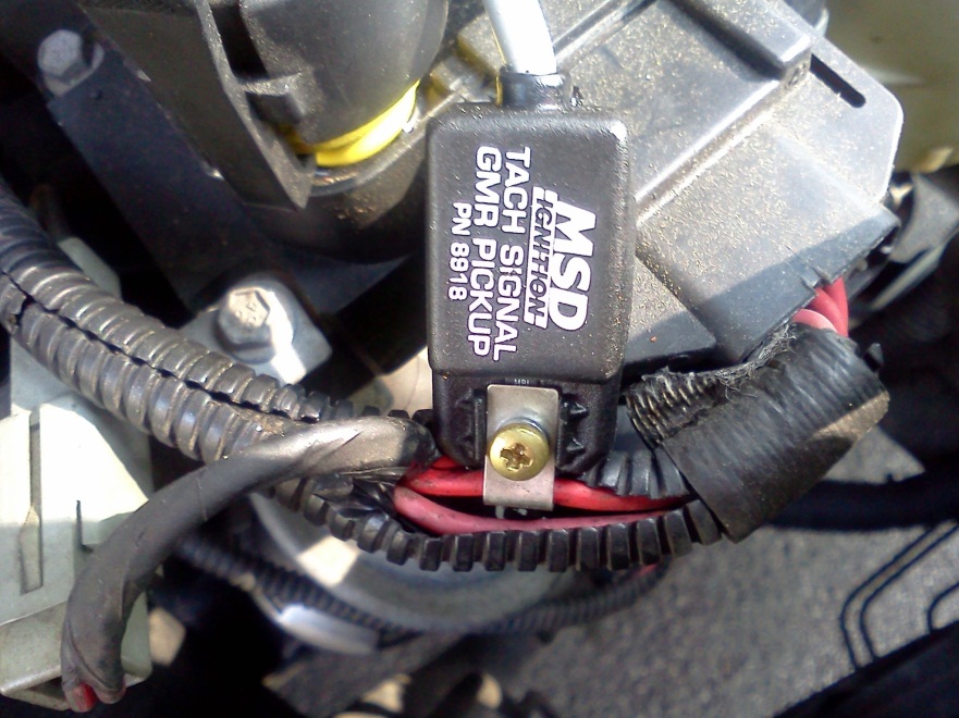
The GMR pickup connects by loosening the small Philips screw on top so that the coil wire can be placed in the middle of the clamp and tightened back down.
Step 9:The MSD digital programmable shift light is now ready to go. Mount the light using the supplied bracket or one of your own, and put the light wherever desired.
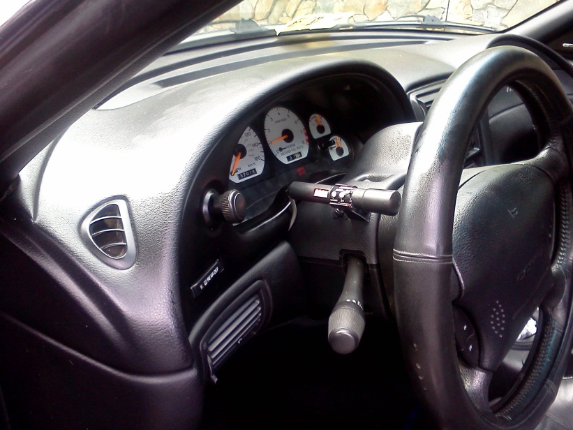
I bought an Autometer column gauge pod to avoid drilling into my stock steering column
Step 10:Reinstall all interior pieces, push the rear window defog switch back in, reconnect and install the gauge cluster, put the trim piece back on, and slide the fog light knob back on (it just pushes back into place).
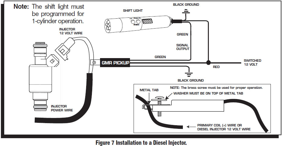
Step 11:Program the shift light as directed in the instructions provided by MSD (added as last page of this guide). Remember that if used with a coil-on plug application, the light needs to be programmed on 1-cylinder mode. If equipped with coil packs (DLI ignition), set the light on 2-cylinder mode.
Enjoy your new programmable shift light!
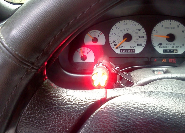
Optional Additional Step: The shit light did not come with a rubber lens to cover the LEDs. I found that you can use furniture tips as a cover; using ¾ inch chair leg tips works perfectly as a cover.
Installation Instructions provided by AmericanMuscle customer Beau Buchanan 8.10.11
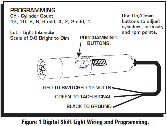
MSD Instructions on Programming:
By pressing the two buttons simultaneously, you get the Shift Light into the different programming modes.
RPM Points:To adjust rpm points, press the two buttons until the rpm shows. Notice that all but one of the numbers flash. The position of the steady digit matches the gear change (the first, second, third or fourth digit equals each gear). Adjust the rpm then push the two buttons again to move to the next gear.
Cylinder Count:The display will read CY and allow you to select between one to 12-cylinder engines using the Up/Down buttons.
Intensity:Control the intensity of the LED and read out. Hold the buttons until LuL displays. Use the buttons to select from 9 (brightest) to 0 to turn off the shift light.
Self:Self mode will walk through all of the settings programmed into the light. It will first show the rpm shift points for the four shifts, the cylinder count and light intensity. Start the test mode by pushing either button once ‘Self’ is displayed. To reset the Self mode, push either button when SELF is displayed, or turn the power Off.
Each time the DSL is powered on, the LED will display the program values that are set.
Related Guides
-
-
Installation
-

