 FREE 1 to 3-Day Delivery on Orders $119+ Details
Best Sellers


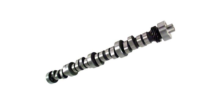
How to Install Comp Cams Xtreme Energy XE264HR Stage I Camshafts on your 1986-1995 Mustang 5.0L
Shop Parts in this Guide
Installation
Important: In order for your new COMP Cams® camshaft to be covered under any warranty, you must use the recommended COMP Cams® lifters and valve springs. Failure to install new COMP Cams® lifters and valve springs with your new cam can cause the lobes to wear excessively and cause engine failure. If you have any questions about this application, please contact our technical department immediately.
Camshaft Installation Procedure
1.Prepare a clean work area and assemble the tools needed for the camshaft installation. It is suggested to use an automotive manual to help determine which items must be removed from the engine in order to expose the timing chain, lifters and camshaft. A good, complete automotive manual will save time and frustration during the installation.
2.Once the camshaft, lifters, and timing chain are exposed, line up the timing marks on the timing gears by rotating the crankshaft. This will position the #1 piston at top dead center (TDC). Next remove the camshaft timing chain sprocket, the timing chain and the camshaft retaining plate if equipped. Remove all lifters and reinstall the cam sprocket to serve as a handle. Slowly and carefully “roll” the camshaft out of the engine.Note: Excessive force is not required to remove a camshaft. If the camshaft does not come out easily, stop! Look for obstructions, such as a fuel pump rod, distributor gear, etc. Do not force the camshaft; something is holding it in the block.
3.Once the camshaft is removed, pull the bottom timing gear off of the crankshaft snout. In many cases you will need a gear puller to remove the crank sprocket. It usually has an interference fit, which may make it difficult to remove without the proper tool. Be careful not to damage the threads in the end of the crankshaft.
4.Now is the time to inspect all of the old camshaft related components (timing chain set, distributor gear, etc.) for abnormal or excessive wear. For example, using an excessively worn
distributor gear with a new camshaft could result in severe engine damage. On flat tappet cams, it is critical that the old lifters be properly disposed of and new COMP Cams® lifters installed. Your camshaft warranty will be voided if old flat tappet lifters are used. With roller cams, roller lifters may be re-used. Inspect them thoroughly; look for any looseness in the wheels and excessive wear on the lifter body.
5.Remove your new COMP Cams® camshaft from its packaging. Inspect all lobes and the distributor gear, making sure the camshaft was not damaged in shipment. Next, compare the stamped numbers on the end of the cam with the spec card to make sure this is the correct cam. It is a good idea at this point to lightly wire brush the distributor gear with mineral spirits or an equivalent solvent. Remember, during the installation process, the cleaner you make your new components, the better chance you have of avoiding failure. Using COMP Cams® Cam & Lifter Installation Lube (Part #103) supplied with your cam, coat all lobes and the distributor gear. It is important to coat the lobes completely, yet not excessively. This same rule applies to the distributor gear and fuel pump lobe. Coat the cam bearing journals with conventional SAE
30 or 40 wt. oil.
6.We recommend you install a new COMP Cams® timing chain and gear set for two very important reasons. First, the old chain is likely to be stretched beyond its service limits. Second, the factory timing set may be machined to retard cam timing. Either of these conditions will detract from the performance that your COMP Cams® camshaft is designed to deliver. Temporarily install the cam sprocket on the camshaft. The sprocket will again serve as a handle to help “roll” the cam into its bearings. Carefully slide the camshaft into the engine, oiling the bearing journals as it slides into the block. Excessive force is not necessary to install the cam. Take your time. Be careful not to scar the cam or cam bearings and try not to wipe away any of the assembly lube as the cam is installed. Once the cam is in, remove the cam sprocket. If the engine is equipped with a camshaft retaining plate, it should be installed at this time. Refer to the engine manual for the proper torque specifications for the retaining plate bolt.
7.Install the new crankshaft sprocket on the snout of the crank. It is recommended to use a Crankshaft Timing Sprocket Installation Tool (Part #4789) for all applications that have an interference fit crank sprocket. If the new camshaft being installed is a hydraulic or solid roller lifter cam, now is the time to check camshaft endplay. For instructions on how to do so, see “Checking Camshaft Endplay” section in this booklet. If the new camshaft being installed is a hydraulic or solid flat tappet cam, this step is not necessary.Flat tappet cams have taper ground into their lobes, which pushes the cam into the proper position and holds it there while the engine is running. Checking endplay is also unnecessary in engines equipped with cam retaining plates, whether the cam used is a flat tappet or roller.
Should you degree your new cam?
It isn’t absolutely necessary to degree the cam for the engine to run efficiently. COMP Cams® grinds most of its High Energy™, Magnum, and Xtreme Energy™ Cams four degrees advanced. This positions the camshaft for the best street performance. However, to assure maximum performance it is recommended to degree the cam. The purpose of degreeing a camshaft is to correct the errors and tolerances in the machining processes of the engine that can affect camshaft timing. COMP Cams® suggests the intake centerline method as the most simple, quick, and efficient way to degree a new camshaft. Instructions for degreeing can be found later in this booklet.
8.Reinstall the cam sprocket temporarily. Check the timing mark alignment in your engine manual. Rotate the crankshaft to its proper position. For instance, the Small Block Chevrolet has a “dot over dot” alignment. Remove the camshaft sprocket and install the new COMP Cams® timing chain. Next, bolt the cam sprocket to the camshaft. Make sure the sprocket is pulled up flush onto the cam. Once again, be sure the timing marks are positioned properly and according to the engine manual. Refer to your manual for the proper torque specifications before tightening the camshaft bolt or bolts. COMP Cams® suggests that Loctite be applied to the threads of the camshaft bolts to assure they remain torqued to the proper specification. This process is very important!Warning: Improperly torqued camshaft bolts can loosen and cause severe engine damage. A camshaft bolt locking plate (Part #4605) is recommended for Chevy 262-400c.i. and 396-454c.i. engines.
9.Remove your new COMP Cams® lifters from the packaging and clean the lifters thoroughly in mineral spirits or an equivalent solvent. Remember, in order to protect your camshaft warranty, new COMP Cams® lifters must be installed on flat tappet cams.It is not necessary to “pre- pump” hydraulic lifters full of engine oil prior to installation and valve adjustment. It is actually undesirable to do so as the “pumped up” lifters will cause the valves to open during the adjustment process, rather than positioning the lifter plunger in its operating position as it is supposed to do. “Pre-soaking” hydraulic lifters in a bath of engine oil is a good idea but not mandatory. Doing so ensures that the lifters are adequately lubricated on their outer surfaces prior to installation. It may also result in a quieter engine start up as the oil in the bath may displace some air from the lifter’s plunger reservoir. Coat the bottoms of all flat tappet lifters with COMP Cams® Cam & Lifter Installation Lube (Part #103) supplied with the cam. Install the lifters, making sure they fit well. Flat tappet lifters should rotate freely in the lifter bores. Any excess clearance or tight lifters can cause damage to the camshaft, leading to engine failure.Note:.0015”-.002” lifter bore clearance is minimum.
10.Clean all pushrods thoroughly because most engines oil through the center of them. If the original pushrods are being used, be especially sure they are clean inside and out. Apply a small amount of COMP Cams® Engine Assembly Lube (Part #102) or equivalent lube on each end of the pushrods and install them into the engine. Clean all rocker arms thoroughly. If the original rocker arms are used, examine each one for excessive wear and replace any that are questionable. Apply a small amount of lube on all contact areas of the rocker arm. With a clean rag or towel, wipe the tips of the valves clean and apply lube to them where the rocker arms will come in contact with them. Also be sure to check the valve stem tips for excessive wear.
11.Install rocker arms. Do not tighten the adjusting nuts down before the proper sequence is performed. On engines with shaft mounted adjustable rocker arms, back off all adjusters completely before installing the assembly. Make sure the pushrod is in the lifter and the rocker arm seat when making valve adjustments.
Hydraulic Flat Tappet and Hydraulic Roller Camshafts: First turn the engine in the normal direction of rotation. Start with cylinder number one (1). When the exhaust valve begins to move, adjust the intake valve to zero lash plus an additional ½ turn more. Rotate the engine over again until the intake valve reaches maximum lift and is almost all the way back down. Then set the exhaust valve to zero lash plus ½ turn. Adjust the valves on each cylinder in this
manner until all valves are adjusted. If the engine has nonadjustable rocker arms, a lifter preload of.020” to.040” must be maintained. See “Non-Adjustable Rocker Arms” section for proper preload instructions.
Mechanical (Solid) Flat Tappet and Solid Roller Camshafts: Follow the same adjustment procedure. Instead of lifter pre-load, use the prescribed valve lash clearance found on the cam specification card. If you have misplaced your cam spec card call COMP Cams® CAM HELP® line at 1-800-999-0853 for the proper valve lash clearance. Mechanical valve lash adjustment is recommended at every oil change.
12.It is very important to “fire” the engine as quickly as possible. The only lubrication that the camshaft and lifters receive is from oil slung off of the crankshaft. First, be sure to use fresh clean conventional SAE 30 or 40 wt. oil and a new filter. Fill the new oil filter with oil before installing. This will allow the engine to achieve oil pressure immediately. Timing the engine properly the first time will be necessary for the engine to start quickly. The following procedure is simple and effective. Rotate the crankshaft in the normal direction of rotation until the number one (1) cylinder is coming up on compression stroke. Align the timing mark on the balancer/dampener to the recommended factory initial timing setting, making sure that both valves on number one cylinder are closed. Install the distributor with the rotor pointing to the number one plug wire on the cap. The engine should fire up as soon as it receives fuel.
Camshaft Break-in Procedure
Important: On hydraulic and solid (mechanical) flat tappet cams that require dual valve springs, the inner spring must be removed during break-in. This allows the lifters to establish rotation and develop a good wear pattern. As soon as the engine fires, bring the rpm up to 2000 to 2500 during the first 30 minutes of operation. Slower engine speeds will not supply the camshaft with an adequate amount of oil for the break-in period. The engine rpm may be varied periodically between 2000 to
2500 to direct oil splash different areas of the camshaft. After the 30 minute break-in period, change the oil and filter again to be sure all contaminants and break-in lube are remove from the engine. The inner valve springs can now be replaced.
If you do not understand any part of these instructions, especially the camshaft break-in procedure, please contact one of our CAM HELP® technical consultants at 1-800-999-0853. We’ll be glad to help you with any problems or questions you may have.
Checking Camshaft Endplay
Camshaft endplay refers to how much a roller cam is allowed to move front to back in the engine. Endplay of.005” to.010” is required to eliminate the possibility of wear occurring as a result of interference between the cam and other engine components. Excessive endplay is detrimental as the cam will be misaligned to the lifter bores, causing the roller wheels on the lifters to run off the edge of the lobes instead of on the center. Another important effect of camshaft endplay is that as the cam moves back and forth, it advances and retards the ignition timing at the distributor gear.
As mentioned, the proper amount of endplay is between.005” and.010.” This can be checked using a dial indicator and magnetic base on the front of the engine. To do this, push the cam as far back in the engine as possible, zero the indicator on the upper timing gear, and then pull the cam as far forward as it will go. The indicator reading is the amount of endplay in the camshaft.
In Chevrolet engines, the front cover must be in place to check endplay because it is the front stop for a roller cam. A cam button is used to take up the additional space between the timing gear and the front cover. These are typically made of Teflon/fiber or steel. The steel buttons have a miniature roller bearing built in. All types are available from COMP Cams® in various lengths, depending on what front cover you are using.
The Chevrolet front cover design makes using the dial indicator technique of determining endplay difficult. Some of the front covers have an access hole with a pipe plug in it to allow a dial indicator extension to go through the hole and contact the upper timing gear. The stamped covers have no such provision. An alternate technique that can be used is to gently insert a long screwdriver in one of the lifter bores and carefully pry the cam back and forth using the sides of the lobe in the bore. Do not use excessive force to try and move the cam. Estimate how much endplay exists from the movement of the lobe, and adjust accordingly. If the endplay is too much, install some suitable shim material behind the cam button and recheck. If it is too small, carefully remove some material from the back of the cam button, reinstall it in the timing gear, and recheck.
One final note of warning: stamped steel Chevrolet front covers are typically very flexible where the cam button contacts them. This is detrimental to maintaining a consistent amount of endplay. Washers are available to weld inside the cover to stiffen it. Also, the water pump fits tightly to some front covers and can act as a support. For most race type roller cam applications the use of a cast or billet aluminum front cover is strongly suggested to eliminate any front cover flex-induced change in endplay. COMP Cams® offers two and three piece billet aluminum timing covers for Big and Small Block Chevrolet engines.
Setting Solid Lifter Valve Lash
Consult the cam spec card for the correct lash specification. All COMP Cams® spec cards list the “hot” (operating temperature) lash setting, but it will also work for initial start-up. Refer to step 11 on how to properly set valve lash.
Setting Hydraulic Lifter Pre-Load
When installing a hydraulic cam, new hydraulic lifters or rocker arms, it is necessary to establish the proper lifter pre-load. Insufficient pre-load will cause excessive valve train noise. Too much pre-load will cause the engine to idle rough or have low manifold vacuum. It is critical to engine efficiency and to the service life of the valve train for the lifters to have the proper amount of pre-load. On any hydraulic camshaft, the ideal lifter pre-load is.030” plus or minus.010.”
Adjustable Rocker Arms:Follow the procedure in step 11 of the camshaft installation instructions to set the proper pre-load.
Non-Adjustable Rocker Arms:A different procedure is required to set hydraulic lifter pre-load on engines with nonadjustable rocker arms. After applying lube, install the pushrods and torque all rocker arm bolts down in the proper sequence and torque specification. Rotate the engine by hand in the normal direction of engine rotation until both the exhaust and intake valves have opened and closed completely. Allow a couple of minutes for the lifters to bleed down.
Using the valve cover gasket surface on the head as a reference point, place a mark on the pushrod. The smaller more defined the mark, the more accurate the measurement. Be sure the reference point you choose for the first mark is easily accessible and easy to duplicate. The pushrod will be marked twice. It must be from the same reference point and angle for the measurement to be accurate.
Loosen the rocker or rocker shaft bolts. Leave the rockers on the head so that they will support the pushrods. Be sure the pushrods are standing free in the lifters, and do not have any pre-load. Using the same reference point, place a second mark on the pushrod. Make sure the angle and reference point are the same as the first mark.
You now have two marks on the pushrod; one with the assembly bolted into place as the engine will run, and the second mark with the lifter unloaded. The distance between these two points will represent the amount of lifter pre-load. If the pre-load is not within.020” to.040,” adjustment is necessary. The simplest way to accomplish this is by using different length pushrods. When measuring to find the correct length needed, be sure to include.030” pre-load that the lifter requires. If the engine uses pedestal mount rockers, shims can be placed under the pedestal to reduce the pre-load. The stands on shaft mounted rockers can also be shimmed in this manner. Longer pushrods will be needed for insufficient pre-load.
In most cases, only one intake and one exhaust pushrod will need to be checked. If the valve stem heights are not equal, then pre-load will have to be checked on each valve. If you do need custom length pushrods, call CAM HELP® at 1-800-999-0853. COMP Cams® offers a variety of pushrods in most lengths.
Rocker Arm Clearance
Rocker arm clearance must be checked at several places. It is very common with higher lift cams to have the rocker arm contact the rocker stud when the valve is in the full open position. Be certain to check this, as lack of proper clearance will cause broken studs, broken pushrods or a worn-out camshaft.
The clearance between the rocker arm and the valve spring retainer must also be checked. This problem will be more pronounced when the valve is closed. The retainer is most likely to contact the underside of the rocker arm right in the center. Be sure to maintain at least.030” clearance at this point. Pushrod clearance must also be checked, especially when using higher ratio rocker arms. The pushrod seat in the rocker is moved toward the stud in this case, so it must be checked at several different lift points for contact with the cylinder head or guide plate.
Valve Springs
The number one factor in premature failure of a new camshaft is an improper or worn-out valve spring. Either incorrect pressure or incorrect spring application will lead to a worn-out camshaft. For this reason, it is highly recommended that the corresponding part number COMP Cams® spring be used with any cam change. Most aftermarket cams have much higher than stock lift. Therefore the stock valve springs will “coil bind” or “stack” before the cam reaches its full lift. This condition will cause the cam to fail immediately. With the valve at full lift, check the clearance between the coils. A minimum of.060” between the coils needs to be maintained.
When assembling the head, check the retainer to valve seal clearance. Sometimes when installing a high lift cam and a different seal, this distance becomes too small. This will bind the valve train and result in camshaft failure. If the clearance does not measure the total valve lift plus.060”, the heads should go to the machine shop and the guides shortened. Excessive spring pressures will also lead to early cam failure. The only way to ensure the correct pressure is to actually check the installed height and have the springs tested. Refer to the specifications on the valve spring box or contact COMP Cams® at 1-800-999-0853.
Piston to Valve Clearance
COMP Cams® strongly urges you to check the piston to valve clearance on the larger street cams and all race cams. The easiest and most accurate way to check this is to place strips of modeling clay on top of one piston, then rotate the engine over by hand with the cylinder head bolted in place and all of the valve train adjusted. If there is any resistance during rotation of the crankshaft, STOP! The piston has probably hit the valve. Then you must decide whether to flycut the piston, or exchange the cam for a profile that will fit into your engine.Note: Minimum piston to valve clearance is.100” on the intake and.125” on the exhaust valves. If aluminum connecting rods are being used, add a minimum of.030” to these suggested clearance figures. Aluminum rods will stretch and expand more than steel rods.
Checking Piston to Valve Clearance
Note: Be sure to check piston to valve clearance after the cam has been degreed. The positioning of the cam in the engine will greatly affect the piston to valve clearance.
1.With the camshaft installed, remove the cylinder head from the block. Clean the combustion chamber and the top of the piston and valve reliefs. The cleaner the piston, the better the clay will stick to it.
2.Apply a strip of model clay 3/8” to ½” wide approximately ¼” thick to the pistons. The clay strips should be placed perpendicular (across) to the intake and exhaust valve reliefs. Applying a small amount of oil to the clay will prevent it from sticking to the valves as they press into it.
3.Reinstall the cylinder head with the head gasket that is going to be used. It will not be necessary to retorque the head yet. All head gasket manufacturers can tell you what the compressed thickness of their gasket will be. Measure the gasket before you install it
permanently and add the difference to the piston to valve clearance. Install a sufficient number of head bolts to secure the head in place while you are rotating the engine. Install the pushrods, lifters and rocker arms on the cylinder you have prepared for the clearance check.
4.Adjust the rocker arms to their suggested clearance. If the camshaft you are checking uses hydraulic lifters, you must temporarily use solid lifters in their place. Hydraulic lifters bleed down and would provide a false measurement. Once the hydraulic lifters are replaced with solid lifters, adjust the lash to “zero.” Be sure not to pre-load the valve spring. Be sure to reinstall the hydraulic lifters before starting the engine.
5.Now turn the engine over by hand in the normal direction of rotation. Be sure to rotate the engine over two times. This will be one complete revolution of the camshaft and assure you of an accurate reading on both the intake and exhaust. Remove the cylinder head from the block. Do this gently, so the clay is not disturbed. It may be stuck to the valves or combustion chamber, so be careful.
6.With a razor or sharp knife, slice the clay cleanly, lengthwise through the depression and peel half of it off the piston. The clay’s thickness in the thinnest area will re"
