 FREE 1 to 3-Day Delivery on Orders $149+ Details
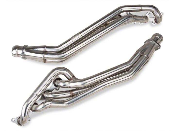
How to install a Pypes Polished Long Tube Headers on your 2011-2012 GT Mustang
Shop Parts in this Guide
Installation
Thanks again for purchasing your new stainless steel Pypes Performance Exhaust Long tube headers. Please be sure to confirm all the components in the kit were received in your shipment before beginning installation. If you find any components missing, please contact our office at 800-421-3890 for replacement. Technical assistance is available both on line at www.pypesexhaust.com or by calling 800-421-3890
Pypes exhaust are designed for the savvy home installer but highly recommends hiring a professional, one that is familiar with the installation of high performance exhaust products. Headers are designed to increase the performance of your vehicle, and as such are designed differently than your stock exhaust system. Extra care must be taken to ensure that hoses, cables, electrical lines, fuel lines, hydraulic lines, or any other objects are not in contact with, or located too close to your installed system.
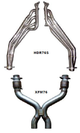
Parts List:
1 Set Pypes long tube headers
1 Set (16) header bolts with washers
4 each collector bolts with washers and nuts
2 each O2 extension cables
1 X-pipe or H-pipe (HDR76SK only)
Work Safe: When supporting a vehicle on jack stands, be sure the ground surface is level and solid, hot asphalt will not support jack stands. Double check your placement before sliding under the vehicle.
Note: Many factors may affect the installation: broken, worn or aftermarket motor mounts, aftermarket suspension components, bent frame or chassis components from accidents, different engines or cylinder heads.
Attention: These items have a highly polished finished which can be marred or scratched during installation. If these products need to be returned and are damaged in any way, you will be charged a 20% restock/polish fee.
Disclaimer: By installing any PPE products, you indicate that you have read the following and agree to these terms:
The purchaser is responsible for following the instructions and safety guidelines set by PPE.
PPE assumes no responsibility for any damages from improper installation, abuse, lack of care or incompatibility with other manufacturers products. The purchaser is responsible for any damage to the products if returned.
These products are manufactured using 304 polished stainless steel. Exhaust heat will turn the finish to a bluish/gold color. This is normal and not a cause for a warranty claim or return.
Warranty: PPE will repair or replace the product at no charge (See enclosed warranty card). We are not responsible any labor charges or shipping fees.
While this installation can be done on the floor with the use of jack stands we strongly recommend that this job be completed utilizing a hydraulic lift. You will need 24 to 30 inches of ground clearance to slip the header into position from the bottom of the vehicle. Please allow the engine to cool for a minimum of 90 minutes before starting the removal and installation steps. The use of safety goggles will protect you from falling debris that may be dislodged from the bottom of the vehicle during the removal and installation process.
Stock system removal:
- Begin by locking the steering column in place so it cannot rotate once the steering shaft is disconnected in a later step. Failure to do so may result in damage to the steering wheel controls if your vehicle is so equipped.
- Remove the battery terminals by starting with the negative cable first followed by the positive. We have found no need to remove the battery and tray but if you choose to it will give you more room to remove and install the top side manifold bolts.
- Remove the strut tower brace bar if your car is so equipped along with the engine cover.
- Loosen the clamp that holds the air inlet tube to the mass air sensor and remove the tube from the mass air. Again we found no need to remove the factory air box but if you feel the need it will gain you better access to the manifold bolts.
- Remove the driver and passenger side O2 connector where it’s secured on the back of the block at the bell housing stud to allow the sensor to be relocated further back.
- Remove the outside nuts holding the cats to the manifolds on both sides as well as the nuts on top of the engine mounts.
- At this time you can raise the car with either jack stands of a hydraulic lift. Again we strongly recommend the use of a lift for the following steps.
- Loosen and remove the 2 rear O2 sensors in the H-pipe and mark their locations so they can be reinstalled in the same positions in your new x-pipe.
- Loosen the butt clamps securing the back of the h-pipe to the factory mid-pipes but do not remove at this time. Next loosen the ball and socket clamps that connect the front of the h-pipe to the factory downpipes.
- Push the exhaust system towards the rear of the car allowing the front of the h-pipe to fall below the factory downpipes.
- Release the factory mid-pipe butt clamps that where loosened in an earlier step by inserting a flat screwdriver under the spring tab and twisting to release while sliding the clamp over the mid-pipe.
- This will allow you to remove the factory h-pipe.
- Next remove the factory downpipes by removing the 2 remaining bolts from the manifold exits.
- Unbolt the plastic oil change access cover under the front of the engine. It is made to be loosened and swing down and hang in place.
- It is now time to remove the stock manifold. Removal of the manifold bolts may be more accessible from either the top or bottom of the vehicle. Start by loosening the steering u-joint at the rack and slide upwards to separate the joint from the rack.
- You can also accomplish this by loosing the rack mount bolts and pulling the rack forward to release the shaft.
- remove the red protective cap on the starter terminals and disconnect the wiring from the terminals. Loosen and remove the 3 bolts that retain the starter. Note two bolts are visible and the third is blind, all three must be removed to get the starter out.
- Next lift the front of the engine up as far as it will go, the bell housing will hit the firewall preventing you from lifting the engine to high. Remove both the left and right engine pedestal mounts at this time.
Installing your new header system:
- Start by using a solvent cleaner to clean the exhaust face surface of the cylinder heads. Take care not to get excess solvent or debris of any type in the ports of the cylinder heads. Also treat the tips of the header bolts with a small amount of anti-seize if you chose to use them.
- Using the supplied gaskets (you may reuse the factory MLS gaskets if they are in excellent condition) apply a small amount of O2 sensor safe high temp. RTV sealant to the cylinder head side of the gasket. This will not only aid in the sealing but also hold the gasket in place. The use of the factory studs is very help full with this step.
- From under the vehicle slip each header into place being careful not to dislodge the gaskets. Start all the bolts holding each header in place. Make sure you start each bolt used a few turns to prevent cross-threading. Tighten all bolts from underneath that can be reached to approximately 20 ft/lbs. If you chose to use the factory studs follow the same procedure using the factory nuts. Note there maybe some bolts that may need to be tighten from the top you can do those when you finish the under car procedures.
- Re-install the left and right engine pedestal mount and lower the engine into position on the mounts. Install the steering shaft and torque the universal joint to 18 ft/lbs.
- Re-install the starter and attach the starter cables including the protective boot. Also swing the oil change cover back in place and re-attach to the frame of the car. Using a small amount of anti-seize on the threads of the forward most O2 sensors install them in the same relative locations as they where removed. Note be careful not to contaminate the tips of the O2 sensors with anti-seize or any other foreign matter that would cause the sensors to malfunction.
- Now it is time to install your Pypes X or H-pipe. This is a full 3” design and if you are reusing the factory 2 -7/8 cat-back system you will have to adapt it to make it work. For the most power gain and sound quality we highly recommend our 3” SFM76M Super System Cat-back system. It is a direct bolt on for our headers system.
- Start by mounting the X/H-pipe with the O2 bungs on a slight angle toward the ground to the ball flange of the header using the supplied 3/8” hardware. Do not tighten all the way at this time. Support the back of the X/H-pipe to make connecting or adapting your cat-back easier. Now you can connect your catback system and make any alignment adjustment. Once you are satisfied with the alignment of your system finish tightening the flanges that connect the headers and the X/H-pipe.
- Install the rear most O2 sensors in the same manor as the fronts with a small amount of anti-seize on the threads. You will use the two O2 extensions on these sensors. Start by connecting the extensions to the sensor lead and then to the factory harness, be careful to rout the extension cable away from any moving part or heat source.
- Connect the front O2 sensor leads to the factory harness. You will have to carefully stretch the factory harness to make this connection. You created plenty of slack in the harness when you removed from the back of the block in an earlier step. Again be careful routing the harness so it is not in contact with any moving parts and heat sources.
- You can now make one more check of all your work under the car before lowering it and moving under the hood.
- Now that the under car is completed start by tightening any header bolt you could not reach from under the car.
- Next re-install the nuts on engine mount as well as the battery and battery tray if you removed it.
- Attach the battery cables and tighten staring with the positive cable first.
- install the intake hose to the throttle body and tighten by reusing the factory clamp.
Final checks:
- Check all work for completeness, bolts tight, connectors connected, lines replaces and clamped ECT. Check that no wires or lines are close to the headers where heat damage could occur or near moving parts. Check for misplaced tools and rags as well as fluid leaks.
- Once you are satisfied with all your checks you can now start your car. Listen for any exhaust leaks. Check around each connection for leaks. If leaks are found make sure that the connections and gaskets are installed properly and the joint or clamp is tightened properly.
- Note in some instances you may experience a check engine light. We have found some models to record slow heat response or temperature errors which in turn set off the check engine light.
This has no adverse effect on the performance or operation of the engine. There are several commercially available tuners and specialty tuning shops that can provide you with diagnostics and advanced tuning capabilities to turn off the light and maximize the performance of your new header system.
As a last maintenance item retighten all bolts and connections as necessary after the system has gone through several heat cycles until they take a set. Periodic checking will add to the longevity of your system.

