 FREE 1 to 3-Day Delivery on Orders $149+ Details
How to install a RAM Adjustable Hydraulic Throwout Bearing/Slave Cylinder on your 2005-2009 GT Musta
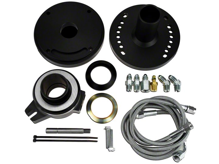
Shop Parts in this Guide
Installation
IMPORTANT! DO NOT RETURN THIS PRODUCT TO YOUR DISTRIBUTOR. If you have questions please review additional materials on our website and/or contact the factory directly
IMPORTANT HYDRAULIC BEARING INSTALLATION INSTRUCTIONS - PLEASE REVIEW THOROUGHLY!
PRE-LUBRICATION OF THE HYDRAULIC BEARING
Before starting, RAM recommends prelubing the piston with hydraulic fluid to make sure you have smooth operation and reduce the chance of damage to the o-rings during the installation. Manually extend the outer housing to its maximum position against the snap ring. Coat the rear of the inner piston with hydraulic fluid then cycle the bearing in and out a few times until it moves smoothly.
BELLHOUSING ALIGNMENT
Your RAM bearing is a floating assembly. Misalignment of the transmission input shaft and engine block will cause o-ring failure. Aftermarket bellhousings MUST be dial indicated to the engine to insure proper alignment. These bellhousings are often not aligned on the center hole to the pilot bearing, and/or squareness top to bottom and side to side. Follow your bellhousing manufacturer's instructions to complete this procedure.
HYDRAULIC FLUID
You MUST use a DOT 3 non-synthetic fluid with RAM hydraulic bearings or damage to the o-rings will occur. If the hydraulic system had another type of fluid prior to installing this bearing, THOROUGHLY flush the system before installing this product. Old, dirty, or contaminated fluid must also be changed.
POTENTIAL CONTACT OF PISTON SNAP RING ON CLUTCH FINGERS
The RAM hydraulic bearing is engineered to be compatible with RAM clutch systems. If you are using a clutch other than RAM, you will need to verify that the bearing piston/snap ring will not make contact with the clutch fingers on your clutch. To check this, bolt your clutch to the flywheel and measure the center hole opening of the fingers. The bearing piston measures 1.620-1.650". Make sure your center hole is larger than this dimension to avoid this contact. If you should decide to remove the snap ring to increase your clearance, special attention must be paid in setup not to overtravel the cylinder and extend it off the end of the piston.
POTENTIAL CONTACT WITH WEIGHTS ON CENTERFORCE CLUTCHES
Verify clearance of the RAM hydraulic bearing cylinder with weights on Centerforce pressure plates. Contact is possible with these units. If you need a compatible pressure plate, contact RAM technical assistance. No warranty will be allowed on bearing cylinders that show evidence of contact with outside sources.
PROPERLY SEALED INLET/OUTLET FITTINGS
The inlet and outlet fittings on the bearing cylinder must be properly sealed to avoid potential leaks. Use Teflon tape ONLY on these fittings. Do NOT use any liquid, PST, or other types of sealants or leaks WILL occur. RAM cannot allow warranty for leaking fittings.
SETUP HEIGHTS/CLEARANCES
Proper setup height is critical to allow for clutch wear and achieve proper clutch release, as well as avoid o-ring damage. Proper setup gap is typically .150-.200".
GUIDE STUD LENGTH
Once you have measured and fitted the bearing, make sure the guide stud is not too long or short by manually extending the bearing to its full stroke and visually inspecting. The bearing must stay on this stud, but the stud length may need to be trimmed to avoid contact with the pressure plate housing.
HARD PEDAL AT THE BOTTOM OF THE STROKE
If you set up the bearing with too much clearance, or use a master cylinder that is too large, the bearing will bottom out on the snap ring. Continuing to push on the pedal at this point will cause the o-rings to blow out of the bearing. Use a pedal stop, adjust the master cylinder rod, or use RAM pedal adjuster 78300 if necessary.
ALUMINUM BEARING SPACERS
Your RAM hydraulic bearing may have shipped with an aluminum collar spacer in 1/2", 3/4" or 1.25" thickness. We have determined that many applications similar to yours require this spacer for proper bearing gap. If you received this spacer, you should install it prior to taking your setup measurements. All applications may not require this depending on your clutch choice.
TROUBLESHOOTING LEAKS
If you should develop a leak with your bearing, it is imperative to determine where the leak is occurring and why prior to removal.
- Check your fluid. Contaminated fluid can cause deterioration of o-rings, which will lead to failure or leakage. The fluid should be clear and free of any debris or water, and should not smell burned.
- Should the fluid appear burnt or have debris, make sure all hydraulic lines are routed away from headers and exhaust that can heat the fluid.
- Remove or pull back the transmission so you have sight access to the release bearing, or allow the bearing to hang and manually push the bearing all the way back into the base.
- Have someone actuate the clutch pedal while you watch. Identify the location of the leak. Make sure it is not coming from any of the fittings, connections, or lines.
Once you have determined the nature of the leak:
- Leaking fittings – remove fittings and re-tape. Make sure tape extends to the end of the fitting but does not overlap the bottom. Securely tighten the feed and bleed lines to the bearing.
- O-rings – after noting the position of the leak, examine the top and bottom o-rings for damage. If damaged, order the proper replacement set for your part number bearing. Change out the o-ring(s) using the instructions listed below under ‘Bearing Disassembly’.
BEARING DISASSEMBLY/O-RING REPLACEMENT
If you must disassemble your RAM bearing for any reason, extreme care must be taken when reinserting the base into the cylinder so as not to damage the o-rings.
- Carefully remove the snap ring on the front of the bearing base.
- When installing new o-rings or re-assembling the bearing, liberally coat o-rings and piston with Parker O-lube.
- Rotate the piston into the housing or install using a press to avoid pinching the o-rings.
- Carefully re-install the snap ring.
REPLACEMENT O-RINGS
Part number for the replacement o-ring set is 78509 (2.615” housing diameter) or 78505 (2.250” housing diameter)
*RAM recommends using Parker ‘O-Lube’ o-ring lubricant for assembly of the bearing. Do not use any petroleum based lubricant as these will damage and deteriorate the o-rings.
UNDERSTANDING AND INSTALLING A RAM HYDRAULIC BEARING IN YOUR VEHICLE
Aftermarket hydraulic bearings are a great way to set up your clutch system in modified vehicles, late model vehicles, or applications where space constraints preclude using a factory mechanical or cable release system. It is critical to understand how these systems work and to get the bearing set up properly to avoid any problems down the road. As your clutch system wears, the fingers of the clutch will get taller or closer to the release bearing. For this reason it is very important to make sure you have the proper gap between the release bearing and fingers of the clutch to start with. The following procedures will guide you through properly determining if the bearing will fit in your car, setting the bearing up, and testing the operation of the system.
DETERMINING THE FITMENT OF YOUR CLUTCH WITH THE RAM BEARING
TOOLS NEEDED
- 18 inch straight edge or steel ruler
- Minimum 6 inch, preferably 12 inch dial (vernier) calipers
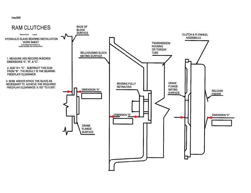
DETERMINE THE CRANK FLANGE PROTRUSION - DIMENSION A
Measure the amount of the crank flange that protrudes from the back of the engine block. This is dimension A in our example and on the bearing setup worksheet.
DETERMINE THE BELLHOUSING DEPTH TO THE RELEASE BEARING - DIMENSION B
REMOVING THE INNER O-RING FROM THE PISTION WILL MAKE CHECKING THE BEARING HEIGHT EASIER. The bellhousing is attached to the transmission and the hydraulic bearing in place with NO shims to do this measurement. Using the straight edge, lay it across the block mounting flange of the bellhousing. Make sure the bearing is in its compressed (shortest) position. Measure from the straight edge down to the release bearing face. Be sure to subtract the thickness of the straight edge. This is dimension B in our example and on the bearing setup worksheet.
DETERMINING THE SETUP HEIGHT OF YOUR CLUTCH – DIMENSION C
Measure the setup height of the clutch assembly. Bolt the pressure plate to the flywheel with the disc so it is exactly as it would be in the car. Set the assembly up on a flat block under the crank flange of the flywheel. Measure from the tip of the clutch fingers, down through the disc center hub, to the block that the flywheel is sitting on. Take an average reading of 3 or 4 positions on the fingers around the clutch. This is dimension C in our example and on the bearing setup worksheet.
DO THE MATH - Sample installation:
Dimension A (crank flange protrusion) = .300”
Dimension B (distance bell face to bearing) = 3.750”
B – A = Available space in the bellhousing 3.450”
Dimension C (setup height of clutch ) = 3.050”
B – C = Dimension D (setup gap) = .400”
In this example, we have a .400” gap between the bearing face compressed and the clutch fingers. The proper setup gap for the release bearing is .150-.200”. Spacer shims will need to be added to achieve this gap.
If the setup gap (D) is less than .150, or possibly a negative number, adjustments will need to be made to achieve proper fit. This may include but not be limited to trimming the collar base of the transmission to allow the bearing to sit back further, or using a spacer shim between the transmission and bellhousing.
Once you have completed these measurements and double-checked your math, you are ready to proceed with testing and installation.
TEST THE BEARING TRAVEL AND PRESSURE CONNECTIONS
The next step is to measure the total potential travel of the bearing as well as check for leaks.
Connect the hydraulic lines to the bearing and the master cylinder. Let the bearing hang under the car and have a helper assist you in bleeding the bearing. You will need to manually retract the bearing back to its compressed position between each stroke of the pedal as the bleeding process is done.
Once bled, you can check the travel of the bearing. Compress it again to its shortest position. From the backside of the bearing, measure with a set of vernier calipers from the outer housing to the inner piston. Record this measurement. Have someone give the pedal a full stroke. Re-measure from the outer housing down to the inner piston. The difference between the starting and ending measurement is your bearing travel.
Example:
TOTAL AVAILABLE BEARING TRAVEL: .800” (fixed)
STARTING MEASUREMENT (COMPRESSED): .050”
ENDING MEASUREMENT (FULL STROKE): .550”
550” - .050” = .500” ACTUAL TRAVEL
Now, this is important! The amount of actual travel plus the clearance (freeplay) must NOT exceed the potential travel number you calculated above. If it does, the bearing will bottom out on the snap ring when operated and cause the bearing to leak from over-pressurization.
Most clutch systems require between .400” and .500” travel to disengage properly. In the example above the bearing would operate correctly. If you do not get at least the .500” travel movement of the bearing, re-bleed the system and test again. If you still do not get adequate travel, it may be necessary to change the master cylinder to a larger bore model to increase the bearing travel to the proper length.
INSTALLING THE HYDRAULIC BEARING
Remove the transmission bearing retainer bolt from the lower-left side opposite the fork opening window of the bellhousing. Replace it with the enclosed stud as needed. The inlet and bleed fittings should be pointing towards the fork opening on the bellhousing.
If you are using the optional remote bleed line kit, replace the bleed fitting on the hydraulic housing with the fitting supplied in the kit. Attach the bleed line to the fitting as it will be routed through the fork hole in the bellhousing.
Secure the 1/8 pipe to #3 and bleed fittings in the bearing assembly. The 1/8 pipe fitting should be located toward the window of the housing when positioned over the bearing retainer. Use of Teflon tape on the fittings is mandatory.
Add shims and re-measure Dimension B until a setup gap (D) of .150-.200 is achieved, or as needed based on your bearing travel measurements.
Slide the hydraulic release bearing over the bearing retainer with the inlet and bleed fittings towards the fork opening in the bellhousing and down over the stud installed in the retainer. The bearing will float on this stud when the slave is operated. Check the stud length by manually extending the bearing to maximum travel. The end of the stud should be about even with the top of the slot in the bearing housing. It may be necessary to trim the stud length to avoid contact with the clutch housing.
INSTALLING THE TRANSMISSION
Lubricate the o-ring on the inside of the bearing assembly base. Attach a #3 line to the inlet fitting and the remote bleed line, if used. Install the required shims on the collar.
Start the bearing on the input collar until the o-ring contacts the collar. Start the transmission into the bellhousing, routing the feed lines into the bellhousing and through the fork hole. As you continue installing the transmission, the bearing will be pushed back into position on the collar.
Now connect the hydraulic feed line and bleed the system thoroughly.
If more or less travel is needed to disengage the clutch assembly, adjust the shims and recheck the position of the bearing on the transmission.
COMPLETE THE INSTALL
At this point you have properly tested and set up your hydraulic bearing and given yourself the best chance for trouble free operation. Finish the install and carefully route the feed line, avoiding headers or other ‘hot spots’ on the car that could heat up the hydraulic fluid. It is a good idea to insulate the feed line to avoid this problem.
IMPORTANT HYDRAULIC BEARING INSTALLATION NOTES - PLEASE REVIEW THOROUGHLY!
PRE-LUBRICATION OF THE HYDRAULIC BEARING
Before starting, RAM recommends prelubing the inner piston with hydraulic fluid to make sure you have smooth operation and reduce the chance of damage to the o-rings during the installation. Manually extend the outer housing to its maximum position against the snap ring. Coat the rear of the inner piston with hydraulic fluid then cycle the bearing in and out a few times until it moves smoothly.
BELLHOUSING ALIGNMENT
Your RAM bearing is a floating assembly. Misalignment of the transmission input shaft and engine block will cause o-ring failure. Aftermarket bellhousings MUST be dial indicated to the engine to insure proper alignment. These bellhousings care often not aligned on the center hole to the pilot bearing, and/or squareness top to bottom and side to side. Follow you bellhousing manufacturer's instructions to complete this procedure.
HYDRAULIC FLUID
You MUST use a DOT 3 non-synthetic fluid with RAM hydraulic bearings or damage to the o-rings will occur. If the hydraulic system had another type of fluid prior to installing this bearing, THOROUGHLY flush the system before installing this product. Old, dirty, or contaminated fluid must also be changed.
POTENTIAL CONTACT OF SNAP RING ON CLUTCH FINGERS
The RAM hydraulic bearing is engineered to be compatible with RAM clutch systems. If you are using a clutch other than RAM, you will need to verify that the bearing piston/snap ring will not make contact with the clutch fingers on your clutch. To check this, bolt your clutch to the flywheel and measure the center hole opening of the fingers. The bearing piston measures 1.690-1.710". Make sure your center hole is larger than this dimension to avoid this contact. If you should decide to remove the snap ring to increase your clearance, special attention must be paid in setup not to overtravel the cylinder and extend it off the end of the piston.
POTENTIAL CONTACT WITH WEIGHTS ON CENTERFORCE CLUTCHES
Verify clearance of the RAM hydraulic bearing cylinder with weights on Centerforce pressure plates. Contact is possible with these units. If you need a compatible pressure plate, contact RAM technical assistance. No warranty will be allowed on bearing cylinders that show evidence of contact with outside sources.
PROPERLY SEALED INLET/OUTLET FITTINGS
The inlet and outlet fittings on the bearing cylinder must be properly sealed to avoid potential leaks. Use Teflon tape ONLY on these fittings. Do NOT use any liquid, PST, or other types of sealants or leaks WILL occur. RAM cannot allow warranty for leaking fittings.
SETUP HEIGHTS/CLEARANCES
Proper setup height is critical to allow for clutch wear and achieve proper clutch release, as well as avoid o-ring damage. Proper setup gap is .150-.200" maximum. If you have not already reviewed the setup instructions, please do so and use these to complete your install.
GUIDE STUD LENGTH
Once you have measured and fitted the bearing, make sure the guide stud is not too log or short by manually extending the bearing to its full stroke and vidually inspecting. The bearing must stay on this stud, but the stud length may need ot be trimmed to avoid contact with the pressure plate housing.
HARD PEDAL AT THE BOTTOM OF THE STROKE
If you set up the bearing with more than .200" gap, or use a master cylinder that is too large, the bearing will bottom out on the snap ring. Continuing to push on the pedal at this point will caue the o-rings to blow out of the bearing. Use a pedal stop or adjust the master cylinder rod if necessary.
ALUMINUM BEARING SPACERS
Your RAM hydraulic bearing may have shipped with an aluminum collar spacer in 1/1", 3/4" or 1.25" thickness. We have determined thay many appplications similar to yours require this spacer for proper bearing gap. If you received this spacer, you should install it prior to taking your setup measurements. All applications may not require this depending on your clutch choice.
TROUBLESHOOTING LEAKS
- If you should develop a leak with your bearing, it is imperative to determine where the leak is occurring and why prior to removal.
- Check your fluid. Contaminated fluid can cause deterioration of o-rings, which will lead to failure or leakage. The fluid should be clear and free of any debris or water, and should not smell burnt.
- Should the fluid appear burnt or have debris, make sure all hydraulic lines are routed away from headers and exhaust that can heat the fluid.
- Remove or pull back the transmission so you have sight access to the release bearing, or allow the bearing to hang and manually push the bearing all the way back into the base.
- Have someone actuate the clutch pedal while you watch. Identify the location of the leak. Make sure it is not coming from any of the fittings, connections, or lines.
Once you have determined the nature of the leak:
- Leaking fittings – remove fittings and re-tape. Make sure tape extends to the end of the fitting but does not overlap the bottom. Securely tighten the feed and bleed lines to the bearing.
- O-rings – after noting the position of the leak, examine the top and bottom o-rings for damage. If damaged, order the proper replacement set for your part number bearing. Some bearing kits include a spare set of o-rings.
- Change out the o-ring(s) using the instructions listed below under ‘Bearing Disassembly’.
BEARING DISASSEMBLY/O-RING REPLACEMENT
If you must disassemble your RAM bearing for any reason, extreme care must be taken when reinserting the base into the cylinder so as not to damage the o-rings.
- Carefully remove the snap ring on the font of the bearing base.
- When installing new o-rings or re-assembling the bearing, liberally coat o-rings and piston with DOT 3 fluid or with approved o-ring lubricant*.
- Rotate the piston into the housing to avoid pinching the o-rings. Pushing it straight on can easily cut the o-rings.
- Carefully re-install the snap ring.
SPARE O-RINGS
Your RAM hydraulic bearing may come supplied with a spare set of o-rings, should some damage occur to the originals during your install.
Part number for the replacement o-ring set is 78505.
Use instructions above for replacement.
*RAM recommends using Parker ‘O-Lube’ o-ring lubricant for assembly of the bearing. Do not use any petroleum based lubricant as these will damage and deteriorate the o-rings.
INSTALLATION INSTRUCTIONS FOR 78175 MUSTANG APPLICATIONS
NOTE: The majority of the setup instructions and notes for this bearing are located on the GENERAL INSTRUCTIONS and INSTALLATION NOTES pages. Please review these thoroughly as well as this additional guide.
Remove the factory bearing from the front of the transmission. Install the RAM collar and spacer using the supplied M6 bolts.
Install the drive stud in the RAM collar. Slide the bearing over the collar.
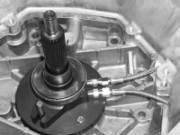
Bearing/collar in place
Follow the directions for setting up the bearing clearance outlined on the GENERAL INSTRUCTIONS page. Re-install the transmission, carefully routing the hydraulic lines. RAM provides an adapter fitting to connect from the bearing to the factory master cylinder. Connect the feed end of the #3 line from the bearing to the #3 end of the adapter. Connect the other end of the adapter to the factory quick disconnect line from the master cylinder.
Route the bleeder line so you have access to the screw and bleed the system. Use only dot 3 fluid. Make SURE that all hydraulic lines are routed away from any heat sources and securely tied. Use heat wrap if necessary. Test the clutch system for release.

