 FREE 1 to 3-Day Delivery on Orders $119+ Details
Best Sellers


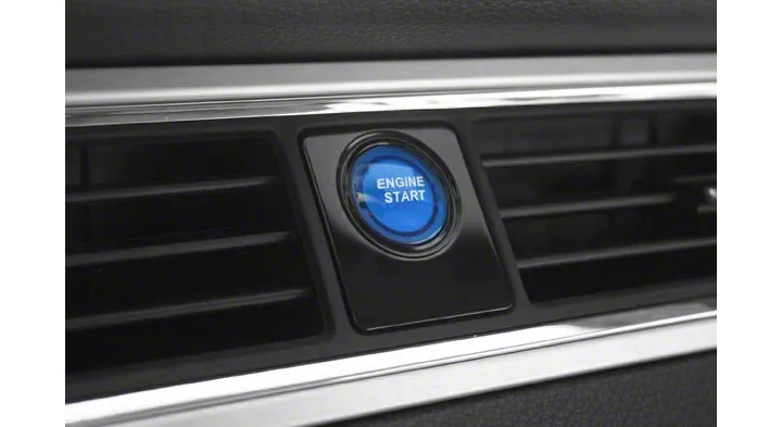
How to Install an SHR Illuminated Push Button Start Ignition Kit - Blue on Your 2010-2012 Mustang
Installation Time
2 hours
Tools Required
- Standard Pliers
- 7mm & 8mm sockets
- Wire Strippers
- 8mm Wrench
- T-20 Torx Bit
- Trim Removal Tool
- Ratchet / Nut Driver & extension
- Small flat screwdriver
Shop Parts in this Guide
Installation
Thank you for your purchase of SilverHorse Racing products. Please read all directions before beginning the installation. A factory shop manual should be available for reference during installation. If, after reading these and any accompanying directions, you feel that you may not be able to complete the installation safely and properly, please seek out professional installation by certified technicians. Please read and understand our product purchase agreement (included on yellow sheet) prior to starting installation. Vehicle should be off and in park with parking brake set prior to beginning installation. Each kit is electrically tested prior to leaving SHR to insure it illuminates and functions properly.
Preliminary Supplemental Restraint System (SRS Airbags) De-power Procedure:
1. With key in the on position, turn off all accessories.
2. Turn off ignition and remove key.
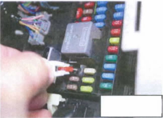
3. At the Smart Junction Box (SJB) behind the passenger kick panel, locate and remove Restraints Control Module (RCM) Fuse # 31. (Fig. 1)
4. Insert key and turn ignition back to on position, but do not start vehicle. Watch the air bag indicator light for at least 30 seconds. The light will remain on without flashing if the correct fuse was removed. If the airbag light does not remain lit continuously, locate and remove the correct fuse before proceeding to next step.
5. Lower windows to the full down position.
6. Turn ignition off and remove key.
7. Open hood and disconnect battery negative terminal with 8mm wrench and wait at least 5 minutes before proceeding. DO NOT have any auxiliary memory savers or power adders connected to vehicle that could inadvertently supply power to the RCM module.
Disassembly Procedure:
8. Lower Steering wheel to bottom of adjustment range.
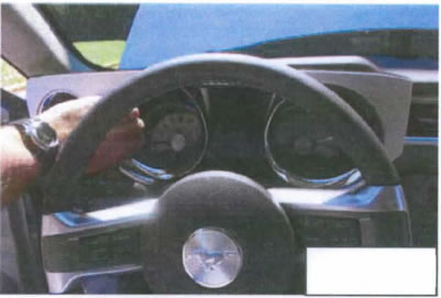
9. Unclip instrument cluster dash cover and driver's side air vent register. (Fig. 2)
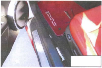
10. Remove Driver's side rocker cover. If equipped with entry lighting, disconnect during removal. (Fig. 3)
11. Using trim removal tool or equivalent, remove tree clip from driver's kick panel.
12. Unclip and remove driver's kick panel.
13. Remove (2) 7mm screws from bottom of driver's side lower dash. Unclip remaining clips and remove.
14. Using a T20 TorxTM bit, remove the three screws on the bottom of the steering column. Unclip the upper and lower sections from one another, and remove steering column covers. (Fig. 4)
15. Disconnect ignition switch wiring connector found on left side of steering column, opposite ignition lock cylinder. Reach behind switch and feel for the connector's release clip to do this. (Fig. 5)
** DECISION TIME ** If you want the switch to be illuminated only when the emergency brake is set and the key is in the ignition. follow steps 16-19. Otherwise. skip to step 20.
16. If car is equipped with a manual transmission, remove shifter knob by rotating counter-clockwise. If equipped with an automatic transmission, using a trim removal tool, gently pry shifter bezel from around automatic shifter and remove.
17. Open center console cover door, reach under center console cover, and unclip / remove center console top section. Disconnect wiring as needed for traction control, ambient lighting, etc ..
18. Remove (2) 7 mm bolts at bottom of radio / HVAC controls face.
19. Reach under and unclip control faceplate. Carefully disconnect electrical connector at bottom of center faceplate and remove faceplate.
Continue Disassembly
20. On passenger side, open glove box, squeeze sides to release stops, and swing glove box down to fully open position
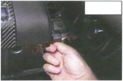
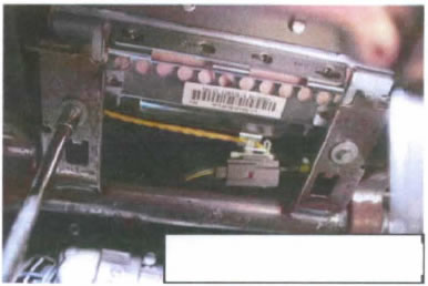
21. Locate 8mm bolts (2) that hold passenger airbag module in place and remove. Any auxiliary modules in the way need to be removed for access to the airbag bolts. (Fig. 6)
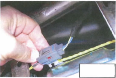
22. Disconnect passenger airbag connector located behind the passenger airbag. (Fig. 7)
23. Without using any tools, work the passenger airbag and dash trim covers loose by hand and remove.
24. Remove the (3) 7mm bolts holding the center register in place
25. Remove center register from dash, and disconnect aux. power outlet plug wiring connector & safely route / secure. Wiring will not be re-used.
26. Remove the aux. power cover door from the center air register assembly.
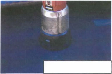
27. Place center register face down on a towel, and release the clips holding aux. power outlet in place. Remove aux. power outlet - it will not be re-installed. Screwdrivers or needle-nose pliers may help aid in removal.{Fig. 8)
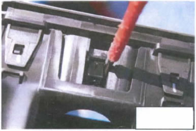
28. Use a small screwdriver to release the clips holding the "push-hold-push-release" door mechanism in place and remove. This is the little 2-prong retainer that normally keeps the aux. cover door closed. (Fig. 9)
Wiring and Pre-Assembly:
29. Route switch wiring through existing power outlet opening in center register. Snap the Tru-Billet switch plate into the existing dash pins that held the original auxiliary power outlet door, and using supplied .050" Allen wrench, tighten set screw to hold Tru-Billet plate in place. Check alignment of plate with face of registers and adjust if needed.
** DECISION TIME ** Decide how you would like switch to illuminate (if at all) and follow the appropriate wiring instruction (30-32) for the ground wire below:
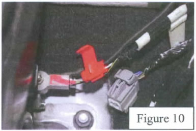
30. If you would like the start button to be illuminated when the key is in the ignition & the emergency brake is set. the ground (black) wire must be pulled from the switch harness split loom and safely routed separately with existing vehicle wiring to the emergency brake switch in the center console. Use supplied zipties as needed to safely route the wire and keep from any sharp edges. Wire will be connected to parking brake switch pin 1 (white wire with violet stripe Fig. 10).
31. If you would like the start button to be illuminated continuously when the key is in the ignition (constant on), the black ground wire will need to be connected to vehicle ground just below instrument cluster near steering column. Keep wire in conduit and only pull it out far enough to reach the distance between the ground point and the steering column ignition switch in upcoming steps. This ground can be shared with any other common ground nearby on the metal portion of the dash.
32. If you do not want the switch to be illuminated at all (constant off). safely terminate the ground wire inside the conduit, and do not connect it to any vehicle ground.
Continue wiring:
33. Red and green wire in conduit (and black wire if following step 32) will need to be safely routed from center console to steering column by routing with existing factory wiring.
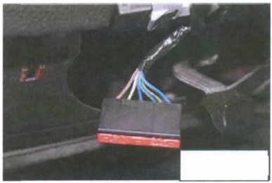
34. Once routed, using supplied tap connector, connect Red wire to Pin 5 of ignition switch (Blue wire with grey stripe tracer Fig. 11)
35. Using supplied tap connector, connect Green wire to pin 7 of ignition switch (Blue wire with white stripe). Important - if you would like car to start ONLY with use of button, cut wire as it exits pin 7, allowing wire as it goes back into the harness to only be connected to green wire. If you would like it to be "dual purpose" and be able to start either with the key (as original) or with the start button (preferred installation method), DO NOT cut blue/white wire, just safely tap into it with supplied tap connector.
36. Once wiring is connected, reconnect ignition switch connector and safely route wiring away from any moving parts. Zip tie to existing factory wiring with supplied zip ties and trim as needed.
37. Reinstall center register in original position and install 7mm screws.
38. Reconnect HVAC control wiring, and re-install center console cover. Re-install (2) 7mm screws at bottom and tighten.
Testing: For the following steps. be sure vehicle is in park if an automatic. neutral if a manual. wheels are safely blocked. and emergency brake is set.
39. Temporarily reconnect battery negative ground cable.
40. Sitting in driver's seat, place key in ignition. If illumination ground wire was connected to emergency brake wiring or directly to ground, start button should illuminate. If it is wired to do so and does not, re-check ground connection.
41. If switch is wired to turn off when emergency brake is released, test for proper operation by doing the following: hold foot firmly on brake pedal and release emergency brake. Illumination should turn off. Set emergency brake and switch should re-illuminate, along with parking brake warning light on instrument cluster.
42. Turn key to on position, but do not start. With transmission in neutral (manual) or park (automatic) and foot on brake, press start button. Engine should start. If it does not, remove key and re-check connections. If engine does start, turn back off.
43. If blue-white wire on pin 7 of ignition switch connector was not cut in step 35, check for "normal" operation with ignition key by attempting to start with key only. Engine should start. Turn engine back off after testing.
44. If above tests are successful, remove key from ignition and disconnect battery ground terminal. Wait 5 minutes before proceeding with re-assembly.
45. Re-connect traction control/trunk wiring to top of center console and re-install console. Close center console door, and if equipped with manual transmission, thread shifter knob back onto shifter.
46. Carefully reinstall passenger airbag assembly and bolt into position. Reconnect passenger airbag wiring.
47. Squeeze sides of glove box together, and close glove box.
48. Remainder of re-assembly is the reverse of steps 14-8. Do not reinstall negative terminal as in step 7 yet.
Final SRS Repower and Testing:
49. Turn ignition switch to "on" position (do not start vehicle).
50. Re-install fuse #31 in the SJB and put covers back on kick panel.
51. While insuring nobody is inside the vehicle, and everything clear of the airbags, reconnect battery ground and tighten terminal.
52. Turn key back to "off" position, wait ten seconds, and then turn key back to "on" (not start) position. Watch the air bag indicator light. If everything is working correctly, the light will stay lit for approximately six seconds, then turn off. If the light does not turn on at all, stays on constantly, or flashes a code after initially staying on continuously for about 30 seconds, there is an unresolved SRS issue that needs to be resolved. Consult a dealer or certified automotive repair facility to diagnose and resolve fault.
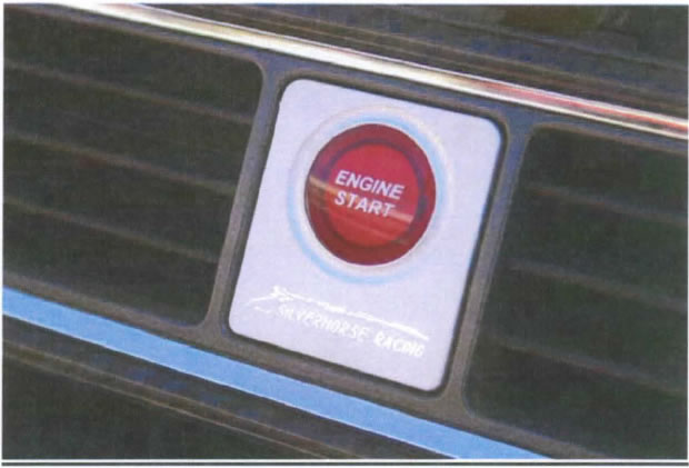
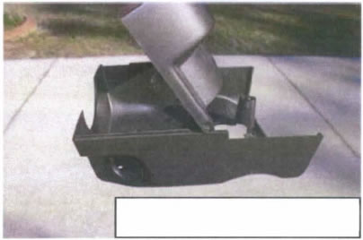
Completed Installation shown above.
Note: The lettering on the button itself is pad-printed (paint stamped). The use of gentle cotton towels moistened with a small amount of water are all that is required to clean the button, should it become necessary. The use of harsh cleaners or abrasive paper towels is not recommend, and can damage the visual appearance of the button as testing has shown.
