 FREE 1 to 3-Day Delivery on Orders $149+ Details
SLP Brake-Control Package ('99-'04 GT) - Installation Instructions
Installation
1. First drain the brake fluid from the master cylinder reservoir by either sucking the fluid out from the top or removing the rear brake line and letting the fluid drip into a cup. If the reservoir is not drained brake fluid will drip onto you and the vehicles exhaust manifolds during the installation.
2. Next disconnect the negative battery terminal.
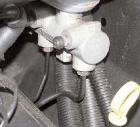
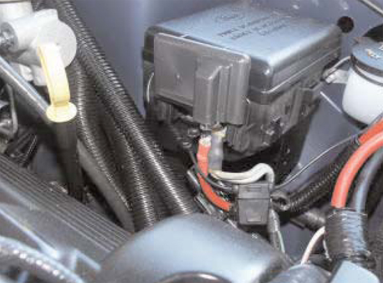
3. Next, remove the brake line that is located in the rear of the master cylinder. To remove this line you must remove the nut that connects the line to the master cylinder and the nut that connects the line to the proportioning valve just below the master cylinder. See photo 1 for location of line.
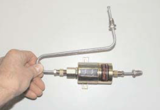
4. On a work bench assemble SLP's solenoid with the two tube nut adapters (using Teflon tape), tighten the two tube nut adapters. Then loosely assemble the brake lines as shown in the photo 2. DO NOT USE TEFLON TAPE ON THE BRAKE LINE FITTINGS.
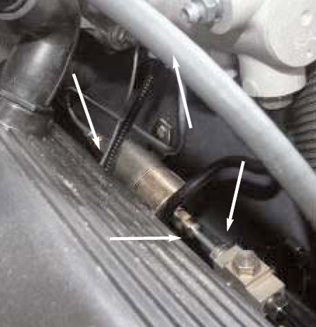
5. Place the assembly into the vehicle and tighten all 4 tube nuts. Two from the brake lines to the solenoid, one on the proportioning valve below the master cylinder and one on the master cylinder. See photo 3 for orientation of line lock assy. and location of 4 tube nuts.
Note:To tighten tube nuts use the modified open ended and line wrenches mentioned above to make tightening of the nuts much easier.
6. After the tube nuts are tight mark with a pen through the slots in the solenoid where the holes are to be located. To be able to drill from the outside of the fender in the wheel well you must measure from a fixed location to the slots in the solenoid that can be seen both inside and outside the fender and wheel well. Measure to the slots on the inside first then on the outside of the fender in the wheel well and mark with a pen. Drill with a 1/4" drill bit.
7. Use the 5mm screws, nuts, washers, and lock washers provided. Put a washer onto the 5mm hex head screw then push the screw through the hole made from the outside or inside of the fender.
8. Next place another 5mm flat washer onto the end of the screw that is sticking through the inside or outside of the fender, then the lock washer, then thread the nut onto the end of the screw. Repeat this procedure for both 5mm hex head screws. Tighten both nuts.
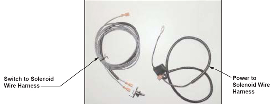
9. Install the supplied wire harnesses. Connect both wires to the two spade connectors on the solenoid by slipping the female spade connectors onto the male spades on the solenoid.
Note:It does not matter which male spade you use to hook up either wire. Reference photo 4 for identification of wires.
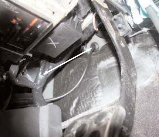
10. After that, route the solenoid to power wire (the wire harness with the fuse connector) to the power stud shown in the photo 5. Remove the nut, insert the eye ring onto the stud and tighten the nut.
11. Then, route the switch to solenoid wire harness from the solenoid through the firewall and into the vehicle. See photo 6 for location of hole through fire wall. In order to insert the harness through the fire wall the switch will need to be taken off of the harness.
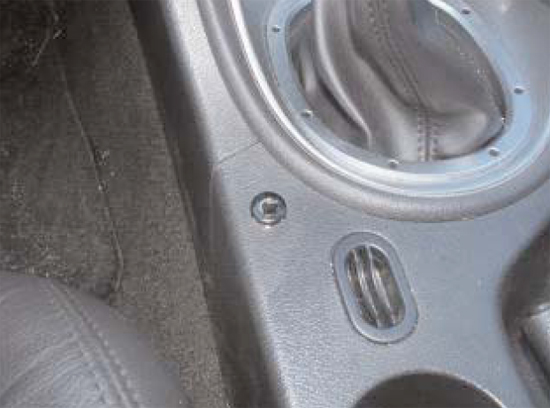
12. Find a suitable location for the switch, photo 7 on the next page shows a good example of a switch location. A drill size of 1/2" will be needed to make the hole for the line lock switch.
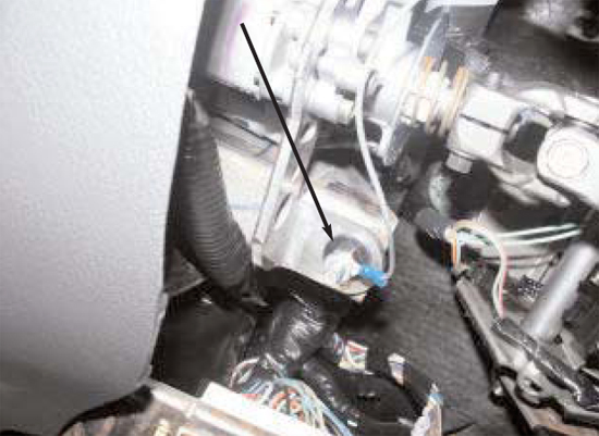
13. At this point, you should install the ground wire. There are a few locations under the driver's side kick panel. Photo 8 is one location.
14. Now, connect the negative battery terminal.
15. Turn the switch on and off to make sure the solenoid is working, you should hear a clicking noise from inside the vehicle with the window open.
16. BEFORE DRIVING THE VEHICLE, BLEED the Master Cylinder and Brake Lines.
17. The installation is now complete.
Installation instructions provided by SLP Performance Parts 5.6.09
Related Guides
-
Installation
-
Installation
-
Installation

