 FREE 1 to 3-Day Delivery on Orders $149+ Details
Steeda Bumpsteer Kit ('94-'04) - Installation Instructions
Installation Time
1 days
Tools Required
- Ratchet 3/8" or 1/2" drive to fit the following sockets
- Sockets 15mm, 18mm deep
- Pliers
- 7/8" wrench for new bottom nut
- 2 Adjustable crescent wrenches
- Hammer
- Floor jack
- 2 Jack Stands
- 2 Drive-on car ramps
- 4 bricks or 2"x4" blocks of wood to chock rear wheels
- Zip ties (12" size)
- PB Blaster or some other penetrating fluid
- Blue thread locker
- Drivers license or credit card (for measurement purposes)

Shop Parts in this Guide
Installation
1. SAFETY PRECAUTIONS: Engage the parking brake and put a 2"x4" block of wood (or brick) in front and behind of each rear wheel to make sure the car cannot move while you are working. Also, walk around the car to make sure you have a clear working space around and under the car.
2. Begin by breaking loose each of the 5 lug nuts on each front wheel, using your mustang’s lug nut wrench. Once they begin to turn, stop and do not continue to loosen them. Next, place your floor jack under the front A-arm (pictured below) and raise your car enough to slide the first jack stand under the frame rail (also pictured below). Next, jack the other A-arm up and slide the second jack stand in place under the frame rail.
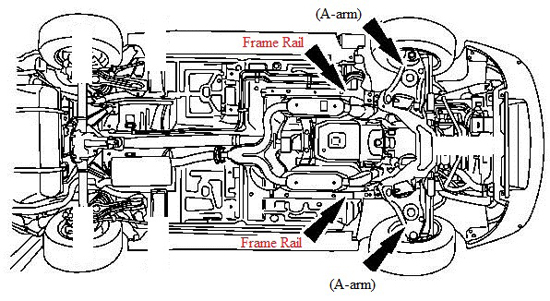
3. Next, remove the wheel lug nuts from both front wheels and take the wheels off. For added safety I always slide the wheels under the frame rails, behind the jack stands. I recommend you do the same.
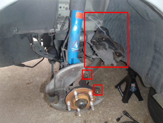
4. Begin the installation on the driver’s side of the car, by removing the brake caliper from the spindle. The caliper is attached by two 15mm bolts. Once these are removed, use a zip tie to support the brake caliper so that it does not strain the brake line. Also, be careful not to drop or twist the caliper so you will not damage the brake line. Next, use the pliers to remove and discard the circular clips on the wheel studs that hold the rotor down. These do not need to be replaced and may have already been removed depending on what work has already been done on the car. Now you can slide the rotor off the hub assembly and set it aside.
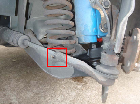
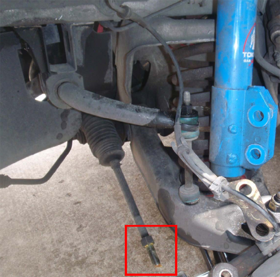
5. Next, you need to break loose the tie-rod nut, which is pictured below. This is where you will need the driver’s license or credit card. First, take a crescent wrench and turn the nut clockwise (looking towards the inside of the car). Once it is loose, place the thin edge of the card in between the nut and the tie-rod end and hand tighten it until the card is lightly sandwiched in between them. Slide the card out and you should have a space the width of the card left between the nut and tie-rod end. This allows you to make sure you get the new tie-rod ends in the same position as the original ones, which means the toe measurement of your alignment will not have changed.
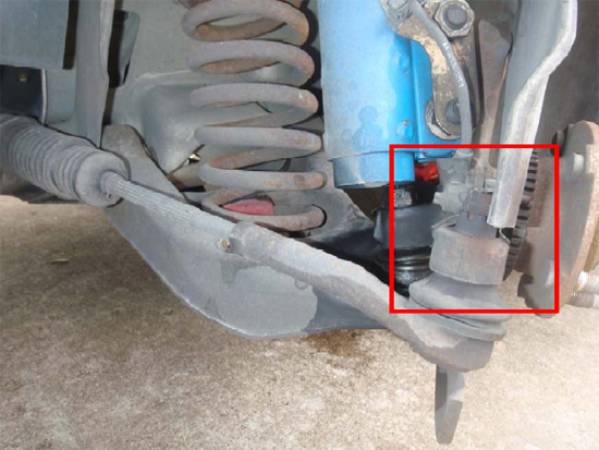
6. Now the tie-rod end is ready to be removed. Straighten and remove the cotter pin that goes through the castle nut that attaches the tie-rod end. Then use an 18mm deep socket and remove the castle nut itself. Now the tie-rod can fall out of the spindle, however, it may require some persuasion. If it doesn’t come out on its own, first, spray it with penetrating fluid. Let it sit for a few Mins and then hit the top of the bolt with a hammer to force it out.
7. Once the tie-rod end is free from the spindle, turn it counter-clockwise until it comes off the tie-rod. You will see yellow grease on the tie rod threads – this is normal. Do not wipe it off or play with it because it will grab and keep any dirt that it comes in contact with, and you do not want that. (Note: My strut is disconnected in this picture because I was doing work on additional components of the suspension system. You DO NOT need to disconnect the strut to
install the bump steer kit.)
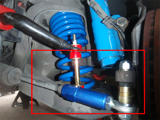
8. Apply blue thread locker to the threads of the silver tie-rod end (with the spherical bushing on the end) and screw it into the blue, threaded sleeve. Refer to the first image of the guide to see which end it goes into. Use two opposing crescent wrenches to tighten these components against each other. Next, thread the other end of the new tie-rod end onto the tie-rod until it is close to the nut. Grab your card again and tighten the blue sleeve until it sandwiches the card between it and the nut once more. Remove the card and tighten the nut back against the blue sleeve; first by hand, then using opposing crescent wrenches.
9. The next step is to take the tapered end of the black, tapered shaft and install it into the spindle. Put the tapered end through the spindle without any hardware on it, then put the 18mm nut on top and tighten it down.
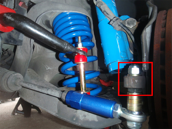
10. Finally, you need to put all the spacers on the black shaft, then slide the tie-rod end bushing over and put the 7/8" nut on the bottom. The picture below illustrates the arrangement.
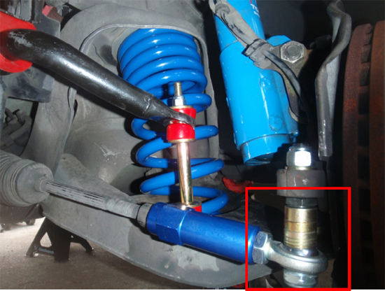
11. The final step for this side of the car is to make sure all the nuts are tight, and then put the rotor and caliper back on. Here is the bump steer kit installed.
12. Repeat steps 4-11 on the passenger side of the car.
13. Next, put the wheels back on and torque the lug nuts down. Lower the car off the jack stands and check the lug nuts.
14. Now you need to adjust the bump steer kit. Drive the front of the car up on your ramps at this time. Looking at the suspension from the front of the car, you want to see what angle the tie-rods are at, relative to the A-arms. You want them to be parallel with the A-arms to eliminate bump steer. Here are three figures which explain the possibilities. In these figures, the blue, thicker, bottom line represents the angle of the A-arm, which remains the same in each figure. It also remains fixed on your car as it sits on the ramps.
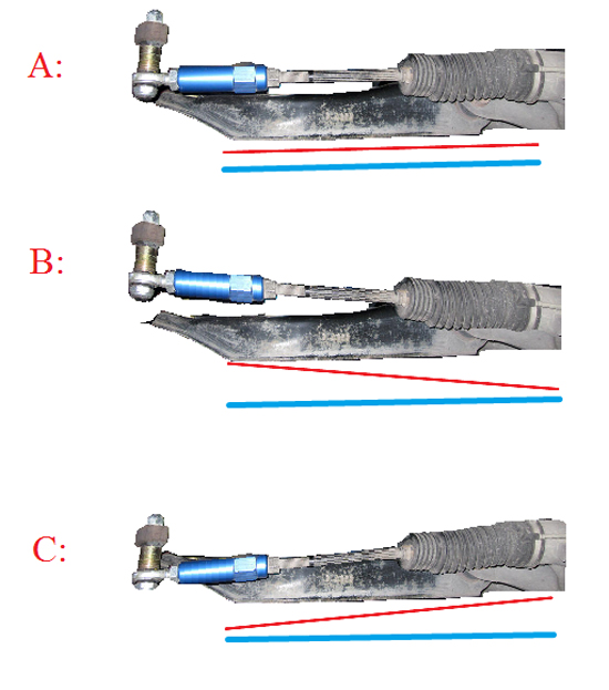
15. Figure A is what you are aiming for. Notice that the distance between the red and blue lines in this figure is the same at any point. This means they are parallel to one another.
16. Figure B shows an example of needing more spacers between the between the spindle and tie-rod end. You should not have this issue when making your first adjustment because you should already have all the spacers in. However, if you remove too many spacers the first time, you may get this result and have to add spacers back in.
17. Figure C shows an example of needing fewer spacers between the spindle and tie-rod end. Notice how the tie-rod needs to be angled upward in order to be parallel with the A-arm.
18. So, your task is to find the correct amount of spacers such that the tie-rod and A-arm are parallel with one another (as in figure A). If you do not want to tighten the nut all the way each time, that is ok. Just be sure you hold the tie-rod all the way up against the spacers so you are checking the correct angle. You can focus on one side and once you get it parallel, you just use the same spacer arrangement on the other side. It is a little tight but you can make these adjustments with the wheels on the car as long as you have the car on ramps. Also, any spacers that do not go between the spindle and tie-rod end, must go on after the tie-rod end and before the nut.
20. Once you have made all the adjustments, tighten the bottom nuts using your 7/8" wrench.
21. Take your car for a test drive and experience the improved handling! If you were careful on the steps that involved the card, you should not need an alignment. However, if your steering seems off one way or another, I suggest getting an alignment to correct it. Congratulations and enjoy!
Installation instructions provided by AmericanMuscle customer Jon David Johnson 10.5.09
