 FREE 1 to 3-Day Delivery on Orders $119+ Details
How to Install a Center Console Mounted Trunk Release Kit on your 2005-2009 Mustang
Installation Time
15 minutes
Tools Required
- Flat head screwdriver
- Phillips screwdriver
- Pliers
Shop Parts in this Guide
Installation:
1. Begin by making sure your car is off and your parking brake is on. Remove any items that may be in your center console, cup holder, glove compartment, or passenger side floor.
2. First, we will remove the center console cover. Remove the two Phillips screws located towards the rear of the center console cover, and set them aside for re-installation later.
3. Make sure your emergency brake is as far up as possible in order to make it easier to remove the center console panel. Note: the rubber boots that shroud the emergency brake lever tend to hug the lever as you attempt to remove the center console.
4. Remove the leather bezel from the shifter (manual transmission) or trim bezel (automatic). This is done by prying up gently on one corner with a small flat head screwdriver. Note: On manual transmissions, you must unscrew the shifter ball in order the remove the leather bezel completely. While unscrewing the shifter ball, hold the leather boot in place so it doesn’t get twisted up.
5. Begin to carefully lift the entire center console. Several clips hold the console into place and they will unsnap as you pull up on the panel.
6. As you lift up on the console, carefully maneuver it over the emergency brake lever.
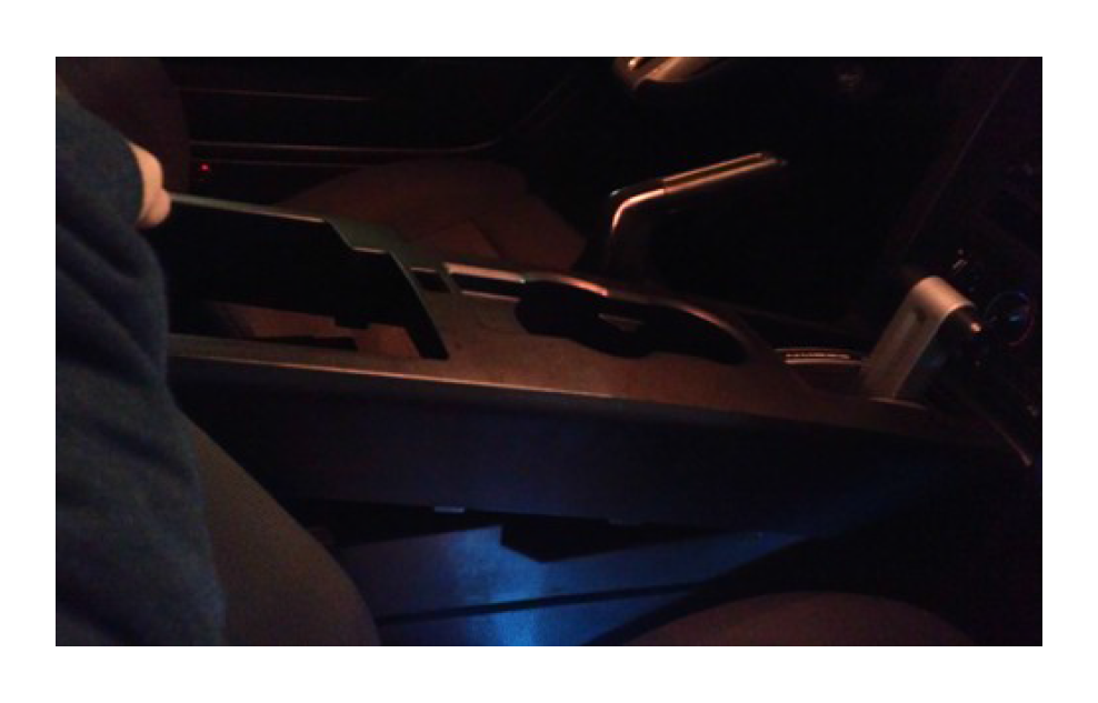
Now that the center console cover is removed, set it aside for re-installation later
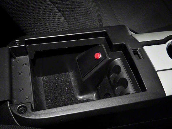
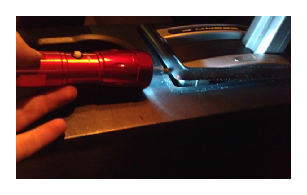
7. Remove the emergency brake access cover with a small flat head screwdriver.
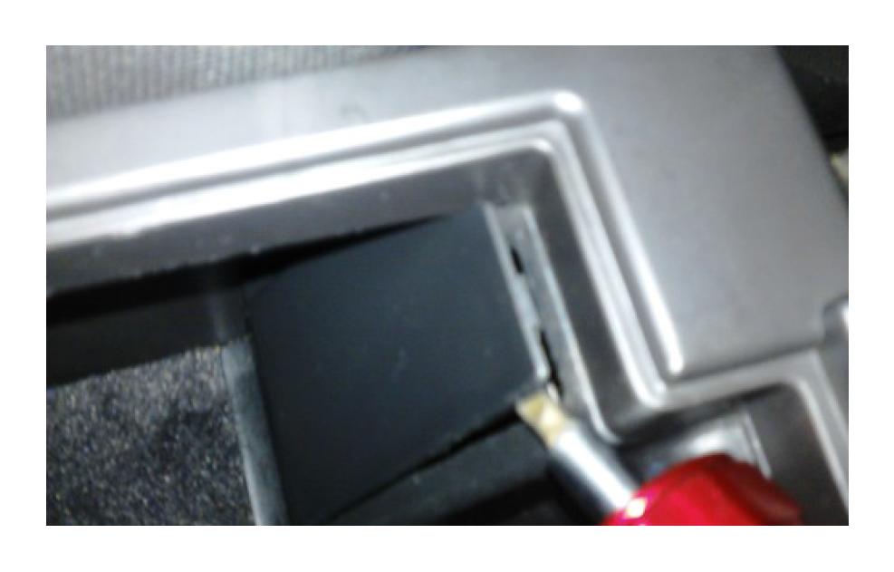
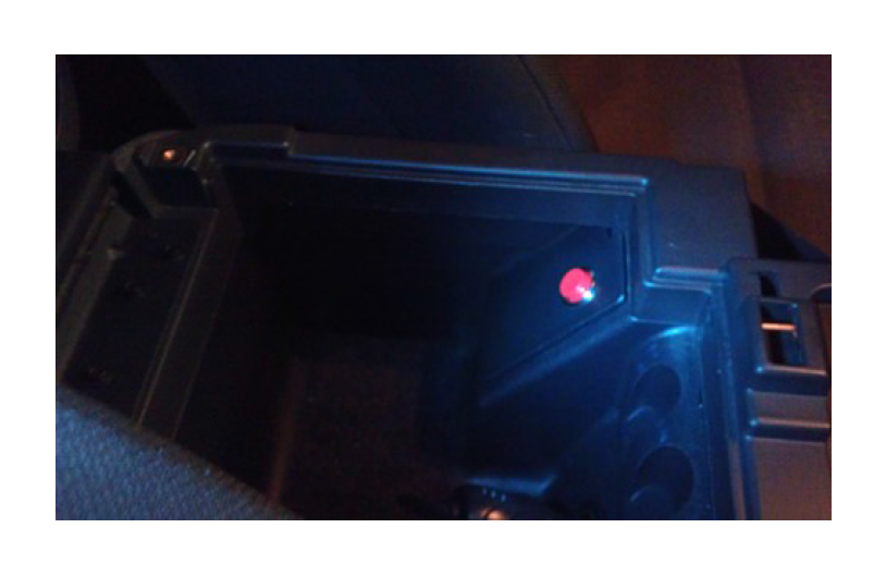
8. Install the included emergency brake access cover (with button) into the center console compartment. Route the wires through the hole vacated by the access cover you just removed.
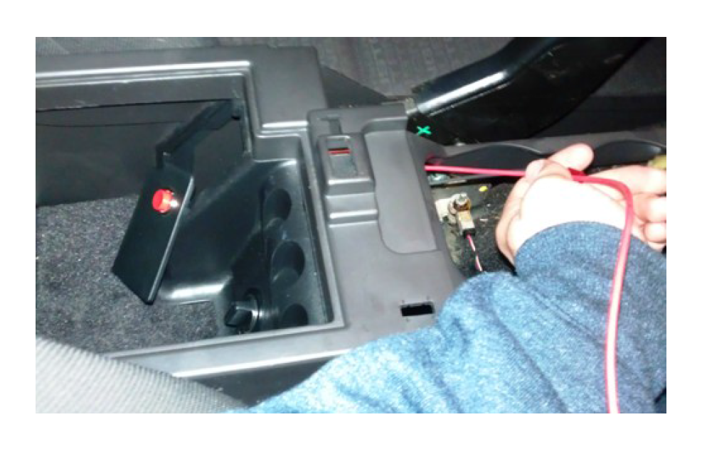
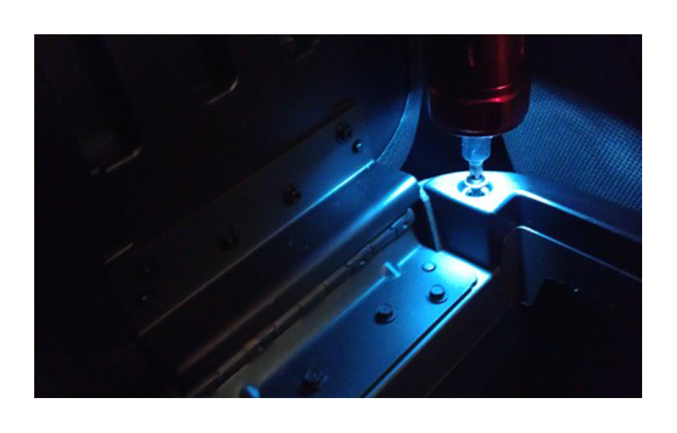
9. Locate the green and black wire running under the cup holder area towards the center console compartment. These wires plug into the 12-volt power supply located in your center console compartment. Place the supplied Blue wire tap onto the Black wire. The wire should sit in the middle of the two teeth. Squeeze down on the wire tap with a pair of pliers until it snaps closed. DO NOT CUT WIRE!!! Plug the Black wire from the button wiring into the back of the wire tap.

Use one or two of the supplied zip ties to safely secure the red and black wires away from the emergency brake, so as not to interfere with E-Brake operation. Tie them to the green/ black wires running to the 12-volt power supply.
Routing the wiring in the passenger compartment:
1. Route the red wire down the passenger side of the center console until you reach the shifter.
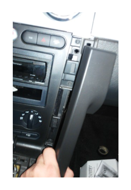
2. Remove the trim panel located to the right of the radio controls. Gently pull the panel straight out as shown in the picture.
3. Now route the red wire underneath the shifter assembly on the passenger side toward the glove box.

4. Re-install the passenger side trim panel to hold the red wire in place.
5. Route the wire across the back of the glove compartment (There is a bracket, which you can secure the wire to with zip ties). Check to make sure that the wire does not interfere with the glove box operation.
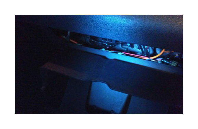
6. At this point remove the passenger side skid plate that says “Mustang” or “SVT” if you have a “GT500.” Some models have this taped down so it might be necessary to pull up firmly; you will hear it snap. Caution: this panel has sharp edges that can cut you, so be careful!
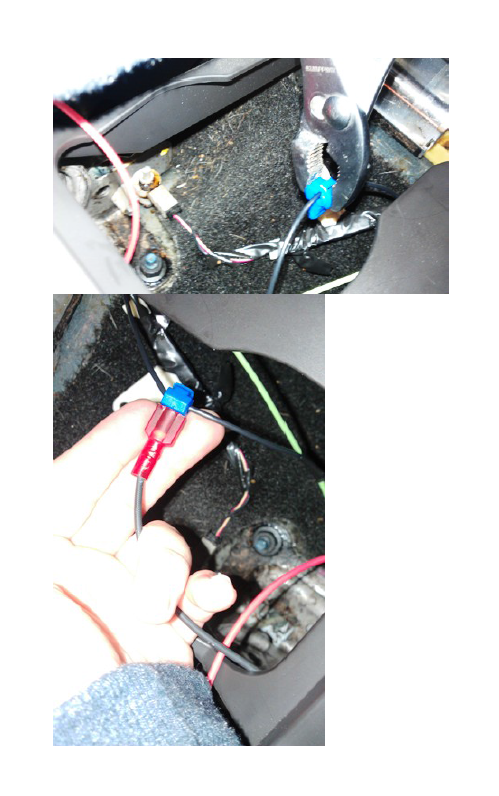
7. Pull back the carpeting slightly to reveal a bundle of wires. Gently peel off some of the electrical tape to reveal all the wires.
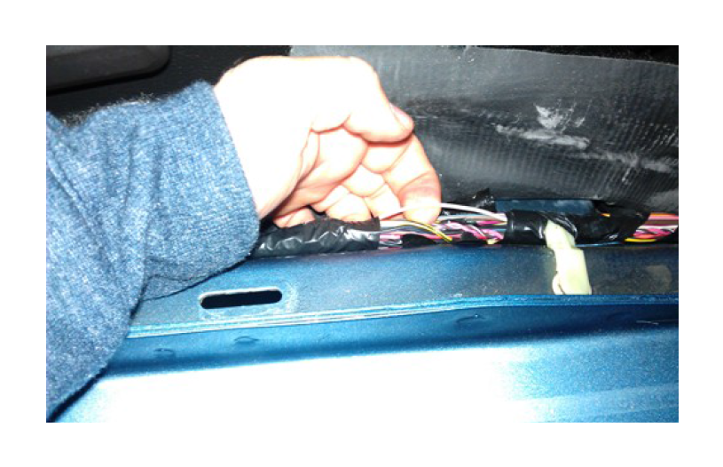
8. At this point it is important to note a few things- sometimes wire colors bleed into each other over the years and it may become tougher to differentiate between the colors. You might also have a tough time seeing the colors because the wires are very small. Lastly keep in mind that depending on the features that your car has, it is possible to have more than one of the same color wire. When this happens, you will always be tapping into the smaller of the two wires (the skinny 22-gauge wire).
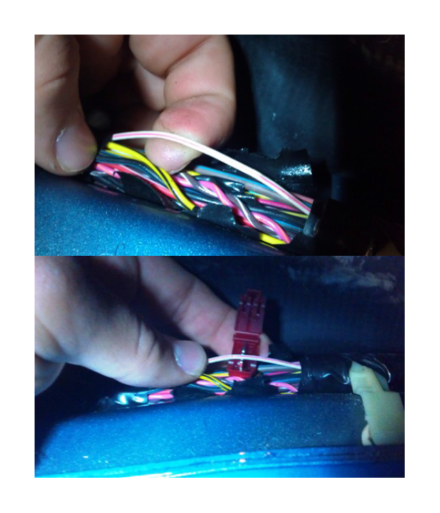
9. Place the supplied red wire tap onto the thin white wire with the pink stripe. The wire should sit in the middle of the two teeth. Squeeze down on the wire tap with your pliers until it snaps closed. DO NOT CUT WIRE!!! Note: The pink stripe on this wire may appear to be red or violet. On 2007 years Ford varied the color of the wire they used. If you find that the white wire with the pink stripe does not exist or does not work, you will most likely need to use the thin orange wire with the pink stripe. In the event that the first wire didn’t work, place a piece of electrical tape over the area that you tapped into.
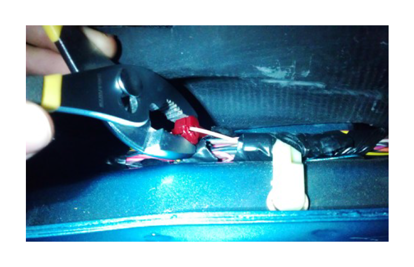
10. Finish routing the red wire down to the skid plate and plug it into the red wire tap. Tuck it in behind the kick panel so that it is out of view.
Final Installation:
1. Double-check everything to make sure it is connected properly. Test the switch to make sure the trunk opens when pressed. If it does not, visit the trouble-shooting guide below; otherwise proceed to the next step.
2. Replace the carpet and then reinstall the skid plate, pressing down until it snaps back into place.
3. Re-install the center console cover the same way you removed it- be sure not to bump the dash.
4. Replace the two screws that were removed from the center console cover during installation.
5. Replace the bezel surrounding the transmission shifter. If equipped with a manual transmission, re-install the shifter boot/ knob.
6. This kit will operate regardless of if the key is in the ignition or not. Be sure not to press it while driving or else the trunk will open.
Enjoy Your Trunk Release Kit!
Trouble Shooting
Trunk does not open when button is pressed:
- Check both wire taps that you installed earlier in installation- make sure both are closed completely, and good contact is made with the wire.
- Make sure you have used the red wire tap on the correct wire- sometimes the small wires make it difficult to determine the correct wire color. As mentioned above, colors can bleed onto other wires over time. Use a magnifying glass to determine the wire color if necessary.
Cannot find the correct color wire on a 2007/08 model year:
- In rare instances, Ford varied the wire colors on some 07/08-model years. Unfortunately, it is not possible to tell if your vehicle has been affected until beginning the installation. If you believe you have a vehicle with this issue and have already tried locating a wire matching the color pattern(s) listed above, the only other way to identify the proper wire is to locate the wire as it comes out of the SJB (Smart Junction Box). To do so follow these instructions:
1. Remove the negative cable on the battery to disconnect the vehicle’s power.
2. Unbolt the SJB so you can gain access to the connectors located behind it- it is located behind the passenger kick panel.
3. Locate the C2280C connector (it is labeled with the part number C2280C).
4. On the connector, locate pin#21- this is the wire color that we are looking for and the one that will need to be tapped into with the red wire tap.

