 FREE 1 to 3-Day Delivery on Orders $149+ Details
Simco 2005-2009 Mustang Gauge Cluster Installation Guide
Installation
1. First disconnect the Negative (-) Battery Terminal and apply the Emergency Brake.
2. Remove the instrument cluster trim by the following steps.
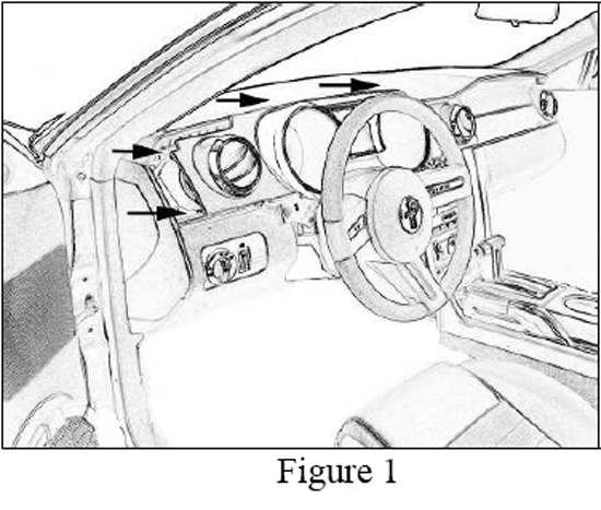
3. Tilt the steering wheel down to its lowest position and remove the Dash Trim from around the cluster by pulling directly outward on the panel (see figure 1). Carefully slide the Panel out from behind the steering wheel and set aside.
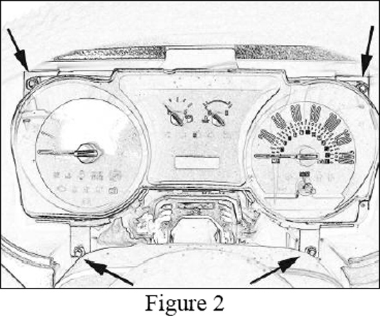
4. Remove the 4 screws from the top and bottom outer corners of the instrument panel with a 7mm nut driver (see figure 2).
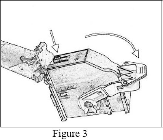
5. Disconnect the electrical connection from the right rear of the cluster. To unlock and remove the connector press down on the locking tab and rotate the arm Clockwise (CW) to eject the connector from the rear of the cluster (see Figure 3).
6. Remove the Cluster from vehicle.
7. Place the original cluster on a clean surface.
8. Remove the original bezel lens from the cluster by the following steps:
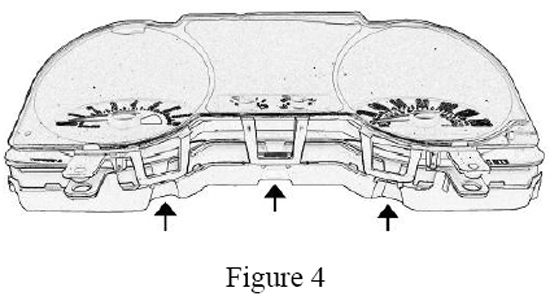
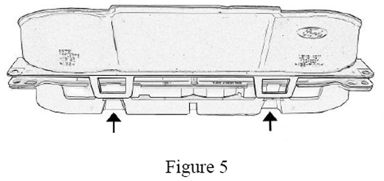
9. Release the 3 holding tabs at the bottom of the cluster and the 2 holding tabs at the top of the cluster (see figure 4 & 5). Then pull the Bezel Lens from the cluster by lifting straight up off of the unit.
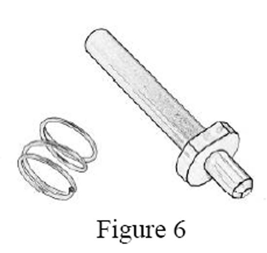
10. For the 4 Gauge/Base level Interior vehicles remove the Odometer Knob Assembly and set these parts aside. This Assembly consists of the Stem and a Small Spring (see figure 6).
11. Remove the original pointers by the following steps:
12. First slow and freely rotate the pointers Clockwise (CW), then bring them back Counterclockwise (CCW) until you feel the resistance when the gauge motor rests on its internal-gear stop. IMPORTANT: When rotating the pointers it is very import to handle with care and rotate in a slow and steady motion. For the 6 Gauge Clusters the Voltage and Oil Pressure gauges will rotate in the opposite directions. They will rotate easily CCW then need to be rotated back CW until you feel the resistance when the gauge motor rests on its internal stop.
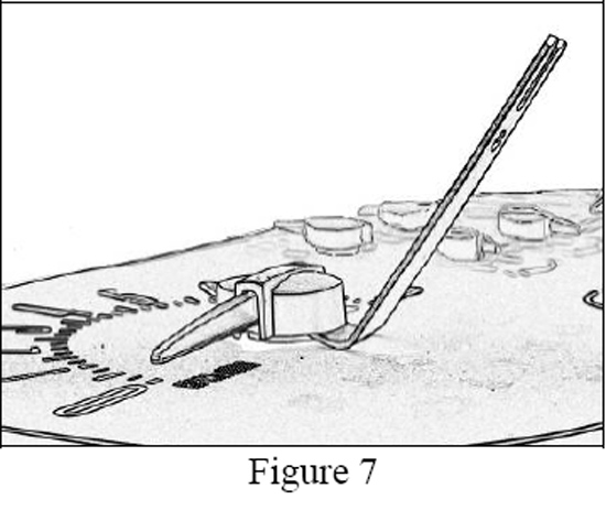
13. Now that the gauges are all resting at their internal stops, position the Pointer Removal Tool by sliding the end marked “Pointer Remover” under the center of the pointer cap until it rests against the center pointer hub (see figure 7).IMPORTANT: It is crucial that the gauges are rotated back and are all resting at their internal stops noted above before removing the Pointers.
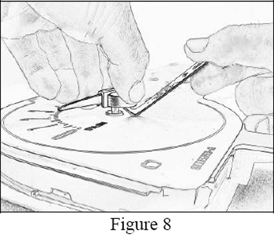
14. To use the Tool properly; keep the pointer level with one hand then push down on the opposite end of the remover tool and lift the pointer straight up while keeping it level to remove it. The pointer should be pulled straight upwards so that the gauge is not bent and damaged (see figure 8). Repeat these steps to remove all the pointers.
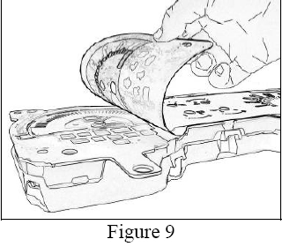
15. Remove the Original appliqué from the cluster by peeling it back from one corner (See figure 9). Pull it slowly making sure that the lighting components underneath do not come out and get disoriented.
16. Install the new Simco Graphic Appliqué with the Rings and Pre-Installed Calibration Templates:
17. First review the cluster lighting components and carefully remove any dirt or debris that might affect the quality of the cluster lighting. Adhesive residue left from the original appliqué should not have an effect on the lighting unless it has become contaminated with debris.
18. Note: Once you place the Appliqué you won’t be able to move it without damaging it do to the strong adhesive. To get a feel of the install you can test the fit and your alignment ability on the cluster before you peel the release liner from the rear of the Appliqué.
19. Next peel the release liner from the rear of the Simco Graphic Appliqué to expose the adhesive, again watch for dirt and debris so that it doesn’t get into the adhesive. IMPORTANT: Do not remove the small Calibration Templates that are located on the front of the appliqué.
20. Locate all the gauge center holes of the new Simco Graphic Appliqué with the centers of the gauges on the cluster. Take your time with the alignment, hold the Appliqué slightly above the cluster while aligning all the holes with the centers, then slowly lower it onto the surface.
21. Once aligned and placed onto the surface, press firmly across the entire front surface of the Graphic Appliqué to completely adhere the part. Be careful not to scratch the painted rings or peel up the Calibration Templates that are attached; using a soft, lint free cloth will help with this.
22. Install the New Pointers by the following these steps:
23. Remove the New Accented Pointers from their packaging. The Long Pointers will be install on the Speedometer and Tachometer gauge locations and the Short Pointers will be installed on the Fuel, Water temp, Voltage, and Oil pressure gauge locations. The 4 Gauge Clusters will not have the Voltage and Oil pressure gauges.
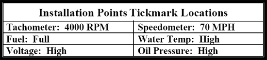
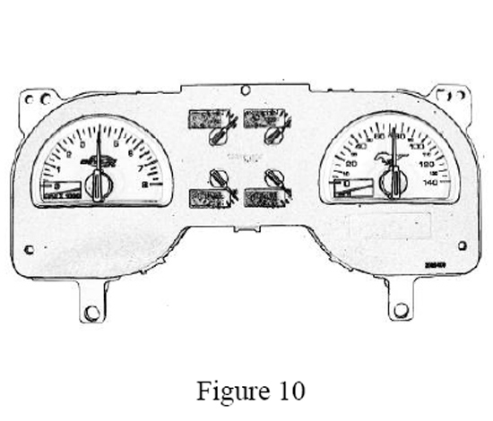
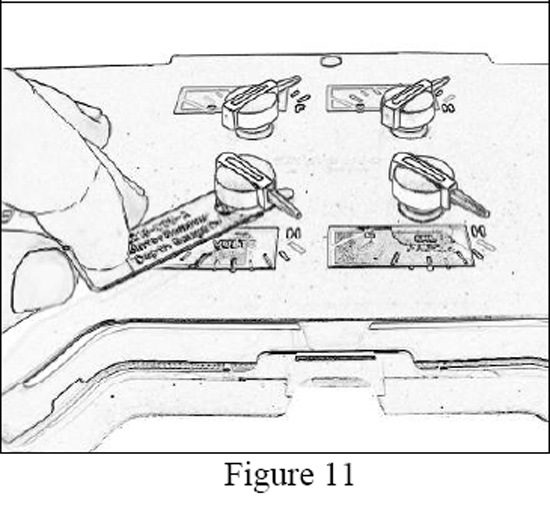
24. Lightly set each of the pointers hubs onto the gauge shafts that are in the middle of the gauge centers while aligning the tip of the Pointer with the “Installation Point Tickmark Locations” that are listed below in chart. (See Figure 10& 11). Do Not push them down yet. It is also not crucial at this point to be exact with these placements:
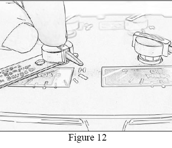
25. Using the “Depth Gauge” end of the Pointer Remover Tool, locate it under the pointer cap and press on the top center of the Pointer Cap pushing straight down until the bottom of the pointer cap rests on the Tool (see figure 12).Important: this tool is too long to fit under the Speedometer and Tachometer pointers without potentially damaging the rings so the opposite end of the tool can be used to support and gage the depth height for these two pointers.
26. Verify that all pointers are setting above the graphic appliqué surface, approximately the thickness of the Pointer Remover Tool (see Figure 12). Make sure that no pointers are rubbing on the appliqué surface. If they are rubbing, Refer to Step 12-14 to remove the pointer, and then re-install the pointer using these above steps.
27. Calibrate the gauges with the new pointers by the following steps:
28. The gauges should all be resting on their internal stops and the pointers located at their “Installation Point Tickmark Locations” listed in Step 24.
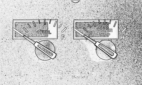
29. Now that the gauges are all resting on their internal stops, slowly rotate a pointer CCW past the internal stop until the pointer blade is lined up with its Calibration Point that is marked on the small overlay. The pointers will rotate on the gauge shafts with light resistance. IMPORTANT: When rotating the pointers it is very import to handle with care rotate in a slow and steady motion. The Calibration Points are represented as a thick line that runs diagonal across the overlay (see figure 13). Remember for the 6 Gauge Clusters the Voltage and Oil Pressure gauges will rotate in the opposite direction.
30.Rotate the pointer easily CW and bring it back CCW until you feel the resistance of the internal stop. The pointer should align with the Calibration Point Line on the overlay. If a pointer was rotated past the calibration point and needs to be recalibrated; this can be done by removing the original pointers: Refer to Steps 11-14. Then re-install the Pointer and Re-Calibrate it: Refer to Steps 22-30.
31. Once all the gauges are calibrated you can then remove the Calibration Overlays by peeling them off. The Overlays will be easier to remove if each one is peeled from left to right. The pointers can be rotated CW out of the way for better access tithe Overlays. Remember for the 6 Gauge Clusters the Voltage and Oil Pressure gauges will rotate in the opposite direction.
32. For the 4 Gauge clusters re-Install the Small Spring and Odo Knob.
33. Re-Install the Bezel Lens by locating it over the cluster and snapping the 5 locking tabs that are around the Bezel to the cluster. Be sure to remove any dust or debris from the cluster face before installing the bezel lens. A soft burst of dry air is the best way to remove dust; otherwise a soft cloth will work.
34. Finally, re-install the Instrument Cluster back into the vehicle (see Steps 3-5 in reverse order). Then re-connect the Negative (-) Battery Terminal.
Installation instructions provided by Simco Ltd.
Related Guides
-
Installation
-
Installation
-
Installation

