 FREE 1 to 3-Day Delivery on Orders $119+ Details
Best Sellers


Simco 1999-2004 Mustang Gauge Cluster Installation Guide
Installation Time
60 minutes
Tools Required
- #2 Phillips Head Screwdriver
- Small Standard Head Screwdriver
- Driver for included T-8 and T-15 Torx bits
- Pliers
- 7mm Socket Driver
Installation
1. First disconnect the Negative (-) Battery Terminal and apply the Emergency Brake.
2. Remove the instrument cluster trim by the following steps.
3. Tilt the steering wheel down to its lowest position.
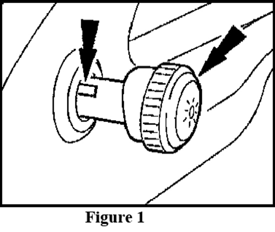
4. Remove the headlamp switch knob by inserting a narrow tool or standard screwdriver in the slot on the side of the headlamp. Slide the tool along the slot moving towards the front end of the knob and pull the knob away from the dash to release the knob from the shaft. (See Figure 1)
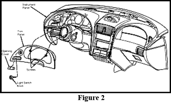
5. Remove the two black screws from the top-inside of the instrument panel trim with a T-15 Torx Bit or a 7mm Socket Driver depending on year of the vehicle. (See Figure 2).
6. Carefully pull instrument panel trim away from the dashboard by pulling directly outward on the panel. Carefully slide the panel out from behind the steering wheel and set aside.
7. Remove the original instrument cluster from the vehicle by the following steps:
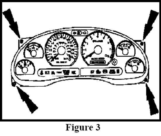
8. Remove the four screws in the top and bottom outer corners of the instrument cluster with a T-15 Torx Bit or a 7mm socket driver. (See Figure 3)
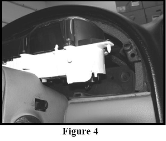
9. Carefully pull the cluster slightly forward and tilt it back and upwards allowing room to remove the two harness connectors. (See Figure 4)
10. Disconnect the two harness connecters from the backside of the cluster.
11. Remove the cluster from the vehicle.
12. Place the original cluster along with the new Simco Instrument Module on a soft clean surface.
13. CAUTION: The circuit board contains sensitive electronic components. Great care should be taken when handling the circuit board. Avoid touching components on the circuit board directly and handle the circuit board by its edges. Static shock could damage the circuit board. Avoid working in areas that can create excessive static shock such as carpeted rooms.
14. Disassemble the OEM instrument cluster by the following steps:
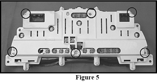
15. Remove six T-15 brass screws from the rear cluster cover and remove the cover. (See Figure 5)
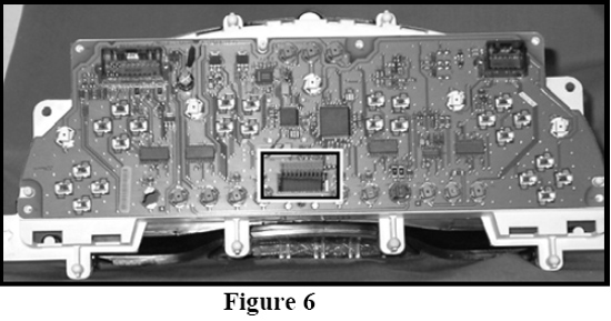
16. Disconnect the digital odometer cable by pulling out from circuit board on the white connector. (See Figure 6)
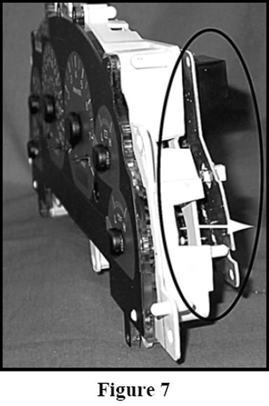
17. Separate the circuit board from the gauge assembly by pulling apart the board while guiding the odometer cable. (See Figure 7)
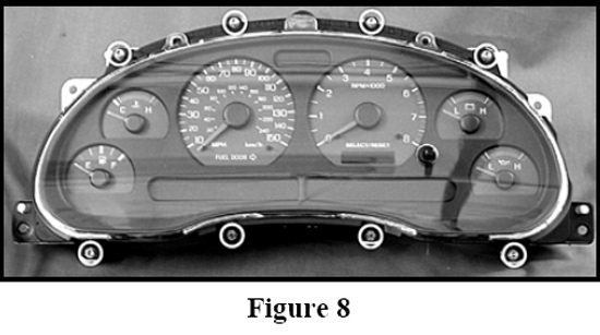
18. Remove eight T-15 brass screws from the front bezel/lens and remove the bezel/lens assembly. (See Figure 8)
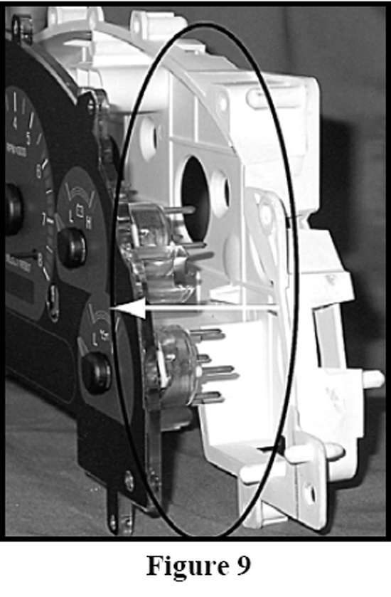
19. Remove the white housing from the graphic & gauge assembly. (See Figure 9)
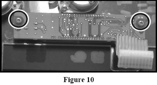
20. Remove two T-8 brass screws from the back of the digital odometer. (See Figure 10)
21. Assemble the New Simco Cluster Module with the OEM cluster parts by the following steps:
22. Attach the digital odometer to the new Simco Instrument Cluster module using the two original T-8 brass screws removed in Step 20.
23. Install the new Simco Instrument Cluster module into the white housing; first, insert the odometer cable back through the housing hole; second, place the NEW lamp connector (already attached to new Simco instrument cluster module) through the top housing hole before seating assembly completely in housing. (See figure 11)

24. Note: NEW lamp connector is solely used as a power source; not intended to be filled with a lamp.
25. Attach the new bezel/lens using the existing eight T-15 brass screws from the original bezel/lens attachment in Step 18.
26. Re-attach the original circuit board by first inserting the odometer cable back through the circuit board hole and then engaging the circuit board into the gauge pins by pressing on the back of the circuit board until it is fully seated to the back of the white housing.
27. Plug the odometer cable back into the circuit board connector from Step 16
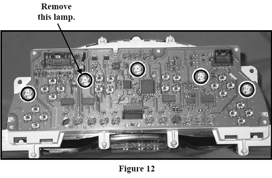
28. Remove the white lamp indicated in figure 12. To remove this white lamp turn the lamp ¼ turn counter-clockwise with a pair of pliers.
29. Plug the new lamp connector into the empty lamp socket as shown. (See figure 13)
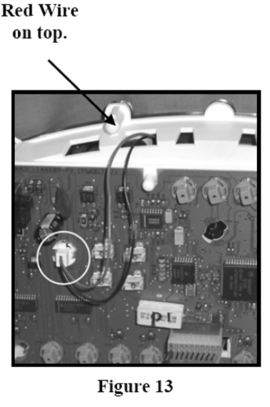
30. Note: The lamp connector MUST have the red wire side facing up towards the top of the cluster when installed.
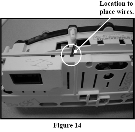
31. Re-attach the back cover using the Six T-15 screws removed in Step 15. Refer to figure 14 for the location to place new lamp connector wire. CAUTION: Do not pinch the new lamp connector wires with the of rear cover.
32. Install the New Simco Custom Instrument Cluster back into the dash by re-attaching electrical connectors, cluster, and instrument panel. (See steps 1-3 in reverse order)
Installation instructions provided by Simco Ltd.
Best Sellers
Related Guides
-
Installation
-
Installation
-
Installation
