 FREE 1 to 3-Day Delivery on Orders $119+ Details
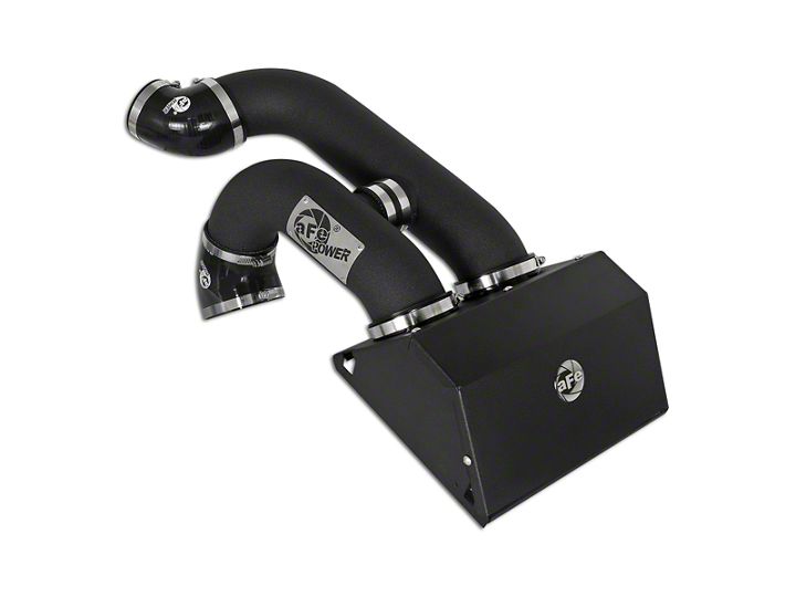
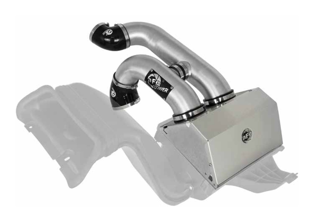
How to Install AFE Magnum FORCE Stage 2 Pro 5R Cold Air Intake - Wrinkle Black (17-18 Raptor) on your Ford F-150
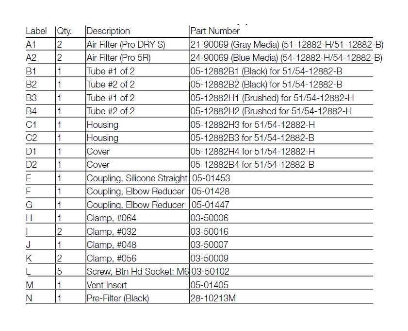
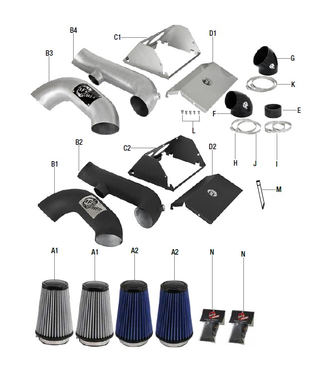
Shop Parts in this Guide
• Please read the entire instruction manual before proceeding.
• Ensure all components listed are present.
• If you are missing any of the components, call customer support at 951-493-7100.
• Ensure you have all necessary tools before proceeding.
• Do not attempt to work on your vehicle when the engine is hot.
• Disconnect the negative battery terminal before proceeding.
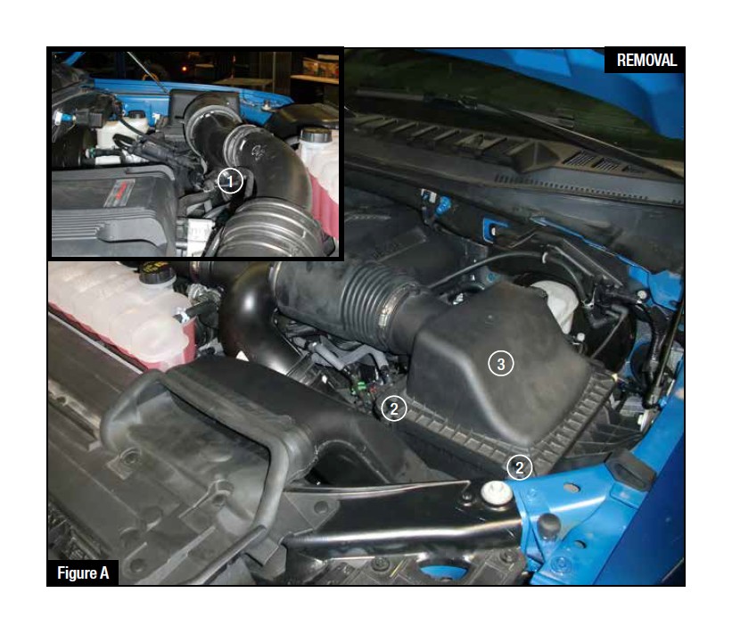
Refer to Figure A for Steps 1-4.
Step 1: Disconnect the Temperature sensor plug from stock tube. 1
Step 2: Loosen the OE intake clamps using an 8mm nut driver from the left and right side runners. 2
Step 3: Unclamp the top portion of the OE airbox. 3
Step 4: Remove the OE intake and the top portion of the OE airbox by pulling straight up and out of the vehicle.
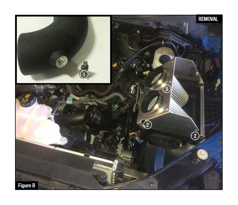
Refer to Figure B for Steps 5-8.
Step 5: Remove the sensor from the OE intake 1/4 turn counter clockwise.
Step 6: Install the sensor on the rear aFe intake tube. 1
Step 7: Install housing and retain with factory clips. 2
Step 8: Install filters from inside the housing. Make sure they are inserted flush and filter retension bumps or groove hold them in place. 3
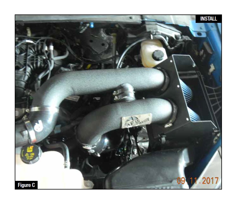
Refer to Figure C for Steps 9-11.
Step 9: Install the small straight coupling on the cross over tube, install clamps but do not tighten.
Step 10: Fit tubes into the remaining couplers. Adjust for best fit and tighten all clamps.
Step 11: Connect sensor harness to the Temp Sensor.
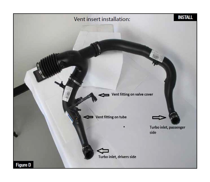
Refer to Figure D for Step 12.
NOTE: (These procedures should be done with the inlet tubes installed on the engine. It is shown off the vehicle for better illustration.)
Step 12: Locate the o.e. plastic tube feeding the driver’s side turbo inlet.
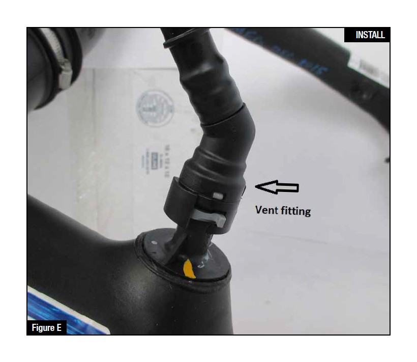
Refer to Figure E for Step 13.
Step 13: Locate the valve cover vent tube that feeds into driver’s side turbo inlet. It is not necessary to remove the engine cover.
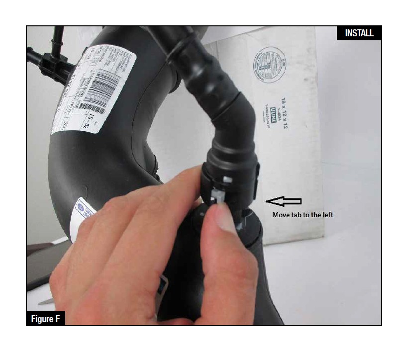
Refer to Figure F for Step 14.
Step 14: Note the release clip on the vent tube connectors. Apply pressure against the exposed tail and pull vent fitting off of the turbo inlet tube. It is not necessary to disconnect at the valve cover end. There is a sensor and wire harness on this vent tube. Do not damage or remove these components.
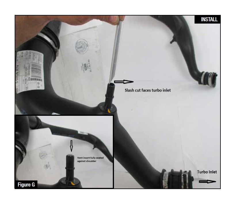
Refer to Figure G for Step 15
Step 15: Insert vent fitting with slash cut facing turbo inlet. It should not be a loose fit. It is direction dependent and must not rotate once installed.
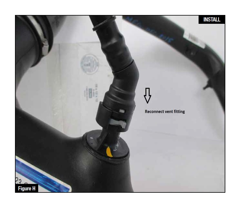
Refer to Figure H for Steps 16-17.
Step 16: Reconnect the vent fitting. It will snap over without having to release the plastic clip. Pull up slightly to confirm installation.
Step 17: Installation is complete. Any codes can be cleared with a code reader or by disconnecting the battery. You will lose any radio presets with battery disconnection.
NOTE: If removal of the vent insert is required, it can be pulled out with internal snap ring pliers.
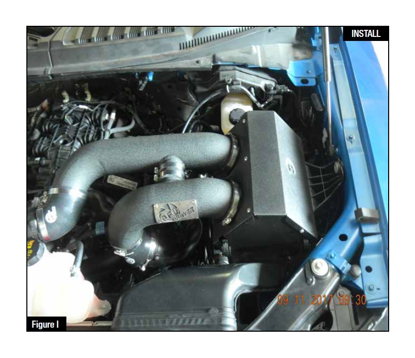
Refer to Figure I for Step 18.
Step 18: Make sure all clamps and screws are tight. Your installation is now complete.
NOTE: Check all bolts, clamps, and connectors after 200 miles.
