 FREE 1 to 3-Day Delivery on Orders $119+ Details
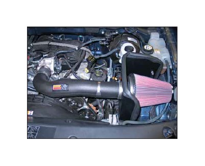
How to Install a K&N Series 63 Aircharger Cold Air Intake on your Ford F-150
Installation Time
1 hours
Tools Required
- Flat Blade Screwdriver
- Ratchet
- Extension
- 10mm Socket
- 3.5mm Allen
- 4.0mm Allen
NOTE: FAILURE TO FOLLOW INSTALLATION INSTRUCTIONS AND NOT USING THE PROVIDED HARDWARE MAY DAMAGE THE INTAKE TUBE, THROTTLE BODY AND ENGINE.
TO START:
1. Turn off the ignition and disconnect the negative
battery.
NOTE: Disconnecting the negative battery
cable erases pre-programmed electronic
memories. Write down all memory settings before
disconnecting the negative battery cable.
Some radios will require an anti-theft code to
be entered after the battery is reconnected. The
anti-theft code is typically supplied with your
owner’s manual. In the event your vehicles’
anti-theft code cannot be recovered, contact an
authorized dealership to obtain your vehicles
anti-theft code.
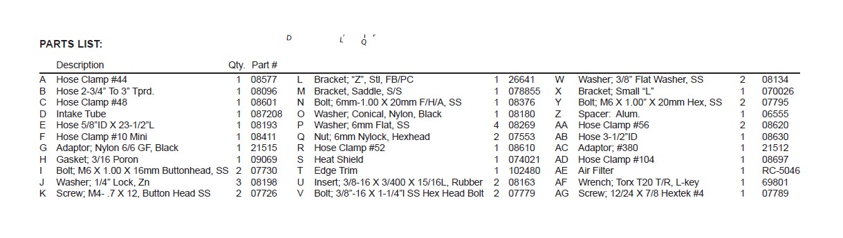
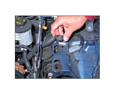
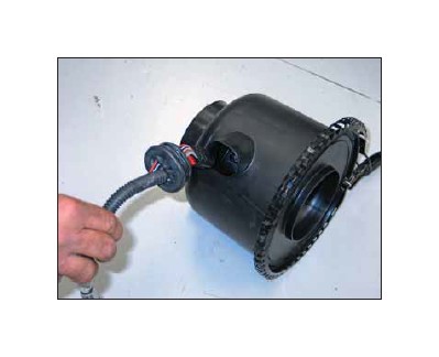
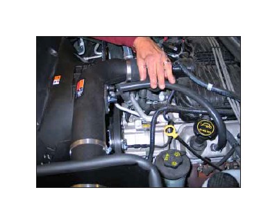
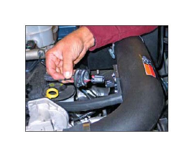
2. Rotate the crankcase vent hose locking rings
and pull the crankcase vent hose off of the valve
cover and intake tube as shown.
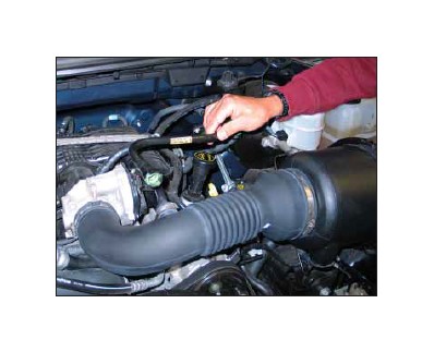
3. Loosen the hose clamps which secure the stock
intake tube to the throttle body and air filter housing
and then remove the intake tube from the vehicle.
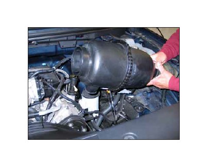
4. Firmly pull up the assembly to unhook it from
the mounting grommets and inner fender as
shown.
NOTE: Use caution as the mass air sensor electrical
harness will still be connected.
NOTE: K&N Engineering, Inc., recommends that
customers do not discard factory air intake.
5. Unhook the secondary mass air sensor connection
from the clip which holds it to the airbox mounting
bracket, and then disconnect the secondary
mass air connection.
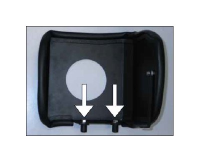
6. Remove the two airbox mounting grommets from
the bracket as shown.
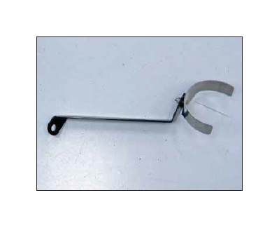
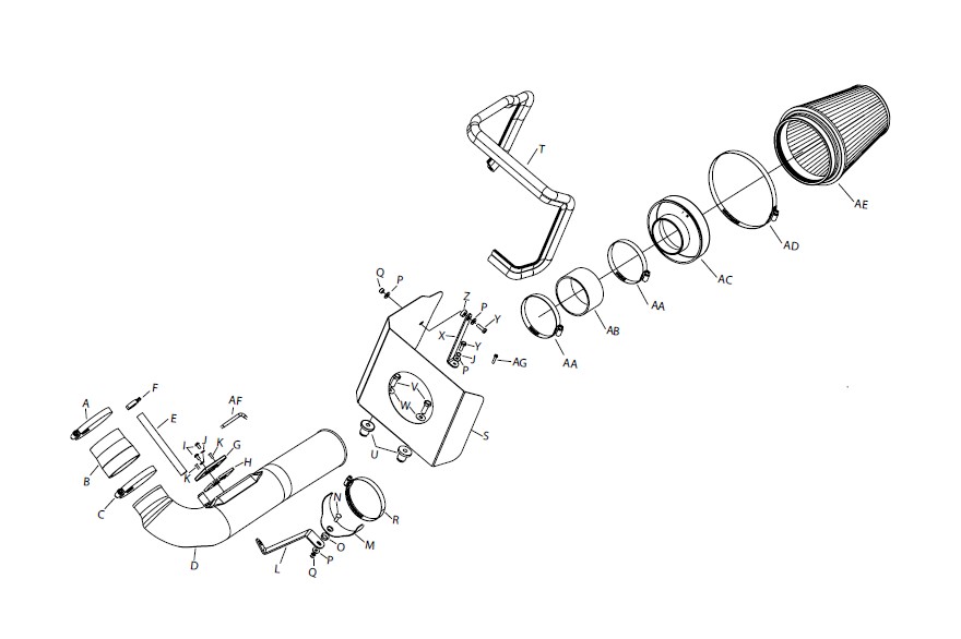
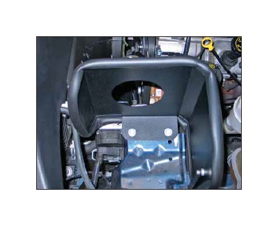
7. Install the saddle bracket onto the tube mounting
bracket as shown.
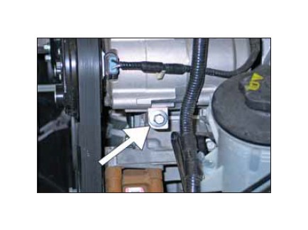
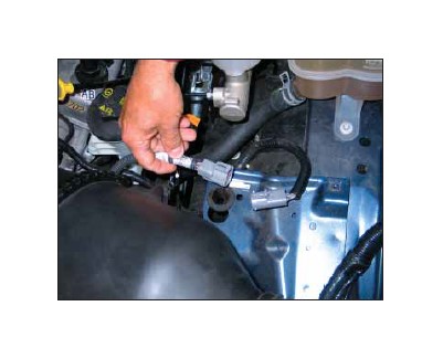
8. Remove the lower front A/C compressor mounting
bolt shown.
NOTE: This bolt will be reused.
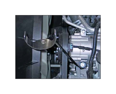
9. Install the tube mounting bracket assembly onto
the A/C compressor using the bolt removed in the
previous step.
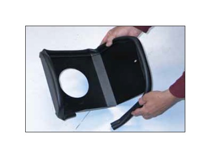
10. Install the edge onto the heat shield as shown.
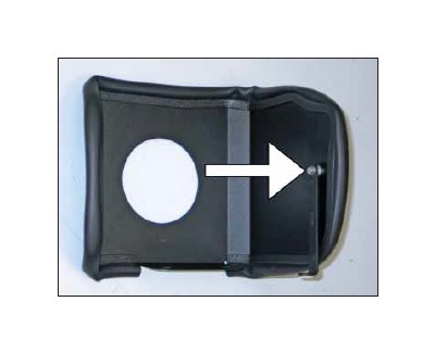
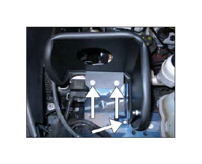
11. Install the heat shield mounting bracket onto
the heat shield with the provided spacer and hardware
as shown.
12. Install the inserted nuts onto the heat shield
with the provided hardware as shown.
NOTE: Do not tighten the bolts at this time.
13. Install the heat shield assembly into position
with the rubber insert nuts installed into the small
portion of the factory holes.
14. Secure the heat shield mounting bracket to
the inner fender with the provided hardware and
tighten the two inserted nuts.
NOTE: Due to vehicle manufacturing inconsistencies,
some vehicles may not be equipped
with the threaded hole in the factory filter
mounting plate. In this case, it will be necessary
to drill a 1/8”id hole in the filter mounting
plate and attach the heat shield mounting
bracket with the provided sheet metal screw.
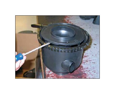
15. Release the clam shell clamp to open the air
cleaner assembly as shown.
16. Slide the rubber grommet back to gain access
to the mass air sensor electrical connector. Using a
small screw driver, release the red locking tab and
disconnect the electrical connection and remove
the wiring harness.
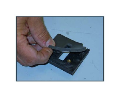
17. Using a flat blade screw driver, push in and
release the mass air retaining plate clips and lift as
shown.
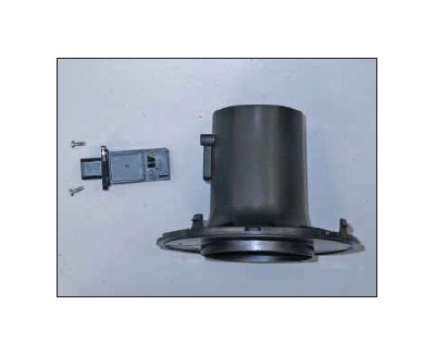
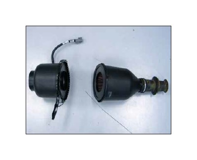
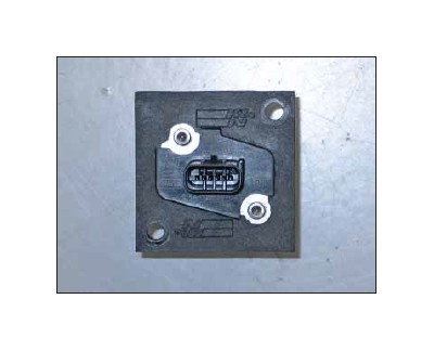
18. Using the supplied T20 TORX, remove the
two screws which secure the mass air sensor and
remove the mass air sensor as shown.
19. Install the supplied gasket onto the mass air
sensor adapter as shown
20. Install the mass air sensor into the adapter using
the provided bolts.
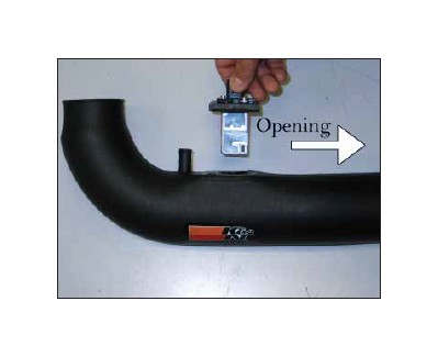
21. Install the mass air sensor assembly into the
K&N® intake tube and secure with the provided
hardware.
NOTE: The opening in the mass air sensor
will point towards the filter end of the tube as
shown.
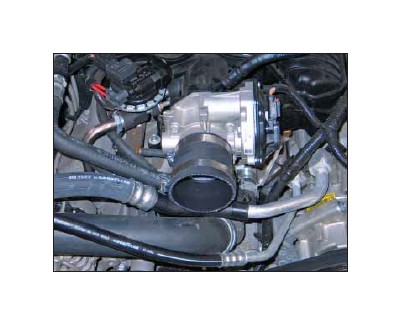
22. Install the silicone hose (08096) onto the throttle
body and secure with the provided hose clamp.
23. Install the intake tube into the silicone hose at
the throttle body and align with the saddle clamp.
Secure the intake tube with the provided hose
clamp.
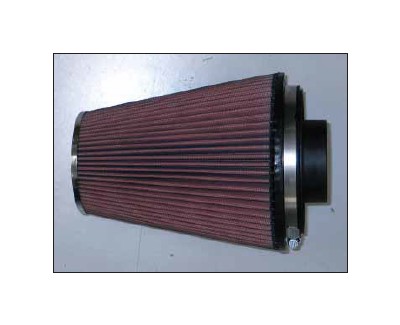
24. Install the filter adapter into the K&N® air filter
and secure with the provided hose clamp.
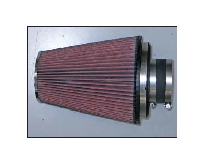
25. Install the silicone hose (08630) onto the filter
assembly and secure with the provided hose
clamp.
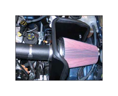
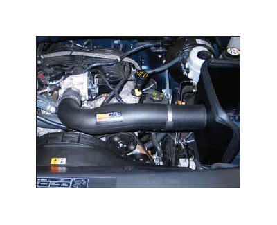
26. Install the filter assembly onto the intake tube
and secure with the provided hose clamp.
27. Install the supplied crankcase vent hose onto
the valve cover and secure with the provided hose
clamp then connect the other end onto the intake
tube as shown.
28. Reconnect the mass air sensor secondary connection
and then reconnect the remaining end to
the mass air sensor.
29. Reconnect the vehicle’s negative battery cable.
Double check to make sure everything is tight and
properly positioned before starting the vehicle.
30. It will be necessary for all K&N® high flow intake
systems to be checked periodically for realignment,
clearance and tightening of all connections. Failure
to follow the above instructions or proper maintenance
may void warranty.
ROAD TESTING:
1. Start the engine with the transmission in neutral
or park, and the parking brake engaged. Listen for
air leaks or odd noises. For air leaks secure hoses
and connections. For odd noises, find cause and
repair before proceeding. This kit will function identically
to the factory system except for being louder
and much more responsive.
2. Test drive the vehicle. Listen for odd noises or
rattles and fix as necessary.
3. If road test is fine, you can now enjoy the added
power and performance from your kit.
4. K&N Engineering, Inc., requires cleaning the
intake system’s air filter element every 100,000
miles. When used in dusty or off-road environments,
our filters will require cleaning more
often. We recommend that you visually inspect
your filter once every 25,000 miles to determine
if the screen is still visible. When the screen is no
longer visible some place on the filter element, it is
time to clean it. To clean and re-oil, purchase our
filter Recharger® service kit, part number 99-5050
or 99-5000 and follow the easy instructions.
