 FREE 1 to 3-Day Delivery on Orders $119+ Details
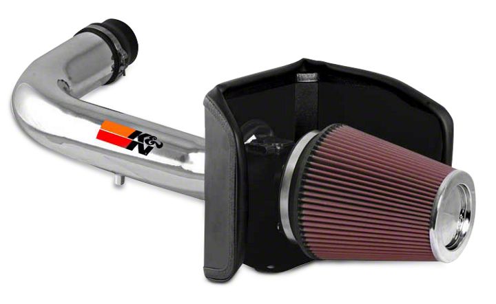
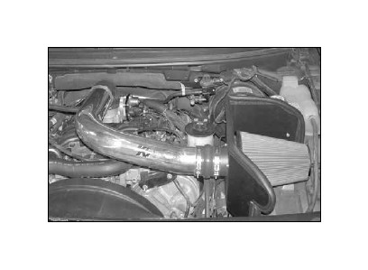
How to Install K&N Series 77 High Flow Performance Cold Air Intake on your F-150
Installation Time
1 hours
Tools Required
- Flat Blade Screwdriver
- Ratchet
- 10mm Socket
- 13mm Socket
- 9/16” Socket
- Torx T20 Driver
- 2.5mm Allen Wrench
- 4mm Allen Wrench
- Drill
- 5/8” Drill Bit
- 1/8” Drill Bit
- Phillips Screwdriver
Shop Parts in this Guide
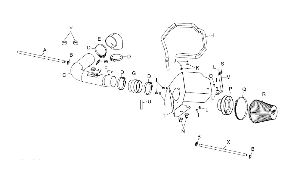
PARTS LIST:
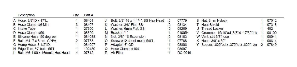
NOTE: FAILURE TO FOLLOW INSTALLATION INSTRUCTIONS AND NOT USING THE PROVIDED HARDWARE MAY DAMAGE THE INTAKE TUBE, THROTTLE BODY AND ENGINE.
TO START:
1. Turn off the ignition and disconnect the negative battery cable.
NOTE: Disconnecting the negative battery cable erases pre-programmed electronic memories. Write down all memory settings before disconnecting the negative battery cable. Some radios will require an anti-theft code to be entered after the battery is reconnected. The anti-theft code is typically supplied with your owner’s manual. In the event your vehicles’ anti-theft code cannot be recovered, contact an authorized dealership to obtain your vehicles anti-theft code.
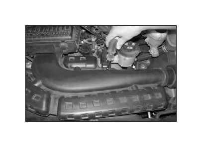
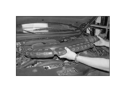
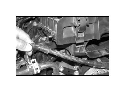
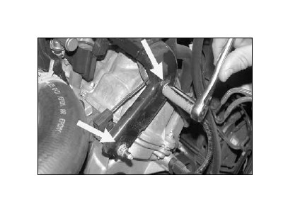
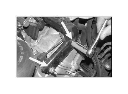
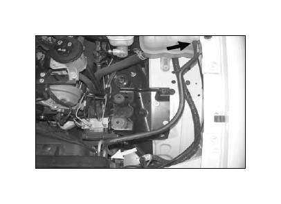
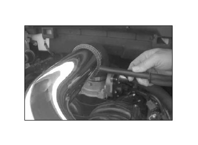
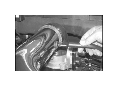
2. Remove the bolt that secures the intake tube to the power steering bracket as shown.
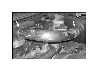
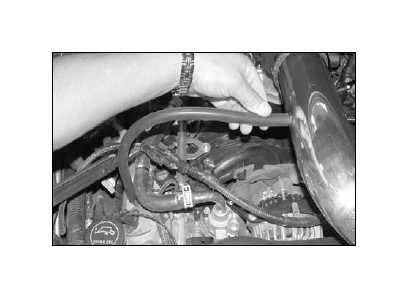
3. Pull firmly on the stock intake tube to release it from the stock air cleaner and the inner fender, then, remove the stock intake tube as shown.
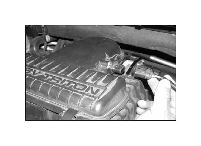
4. Disconnect the mass air sensor electrical connection as shown.
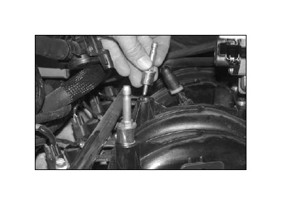
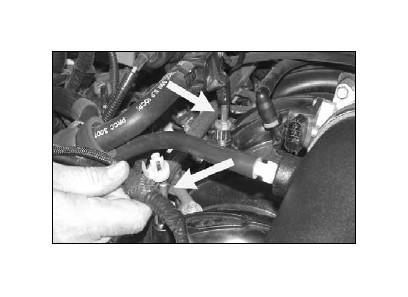
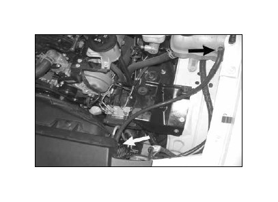
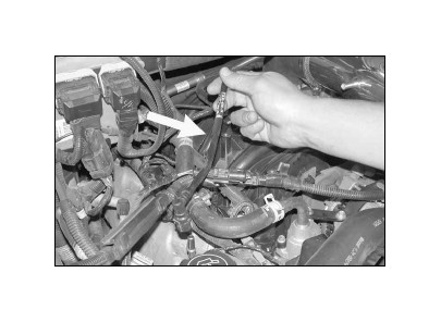
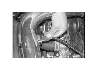
5. Disconnect the crankcase vent hard line from the air cleaner as shown.
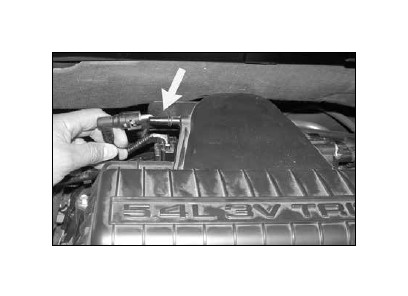
5a. Disconnect the brake booster vent line from the air filter housing as shown.
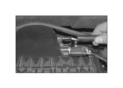
6. Unclip the wire harness from the air cleaner as shown.
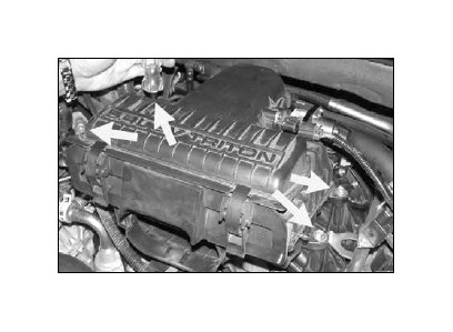
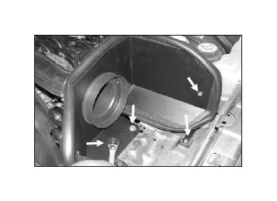
7. Remove the four bolts that secure the air cleaner as shown.
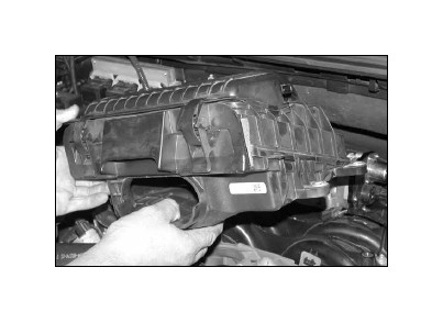
8. Pull firmly upwards to remove the air cleaner as shown.
NOTE: K&N Engineering, Inc., recommends that customers do not discard factory air intake.
8a. Re-install the factory airbox mounting studs with the provided spacers as shown.
8b. Re-install the heater control valve and wiring harness mounting clips onto the airbox mounting studs as shown.
9. On vehicles equipped with the intake tube support bracket, remove the two nuts and then remove the stock intake tube support bracket as shown.
10. On vehicles equipped with the intake tube support bracket, reinstall the two nuts removed in step nine as shown.
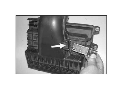
11. Remove the mass air sensor from the stock air cleaner as shown.
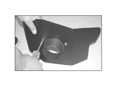
12. Apply the provided thread locker onto the provided hardware and secure the filter adapter onto the heat shield as shown.
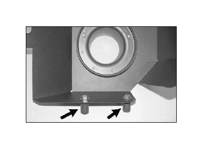
13. Install the provided rubber inserts, hex bolts and washers onto the heat shield as shown, but do not tighten at this time.
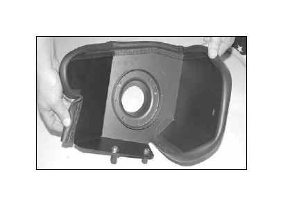
14. Install the provided trim seal onto the heat shield and trim to fit as shown.
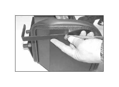
15. Install the provided “L” bracket onto the heat shield using the provided hardware as shown.
15a. Loosen the coolant recovery hose, hose clamps, and then remove the factory recovery hose shown. Be sure to catch any coolant, which flows out of the radiator during hose removal.
NOTE: Be sure to let the engine cool completely before removing the overflow hose or hot coolant will escape from the radiator and injury or damage may result.
15b. Install the supplied coolant recovery hose and secure with the provided hose clamps.
NOTE: Be sure to replace the coolant that was recovered during hose removal by replenishing it in the coolant recovery tank.
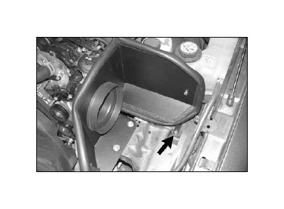
16. Install the heat shield into the vehicle and secure the “L” bracket to the threaded hole on the inner fender using the provided hardware as shown but do not tighten at this time.
NOTE: Due to manufacture inconsistencies, some vehicles may not be equipped with threaded hole in the factory filter mounting plate. It will be necessary to drill a 1/8” hole in the air filter mounting plate and attach the heat shield bracket with the sheet metal screw provided.
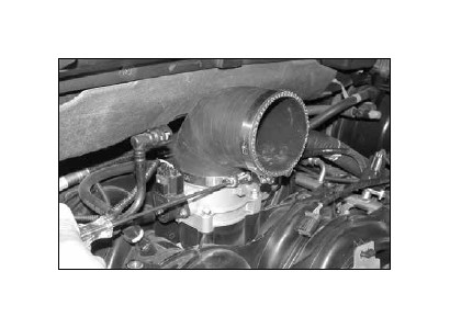
17. Install the 90° silicone hose and hose clamps onto the throttle body as shown but do not tighten completely at this time.
NOTE: The hose has one short leg and one long leg, the short leg goes on the throttle body and the long leg goes to the intake tube.
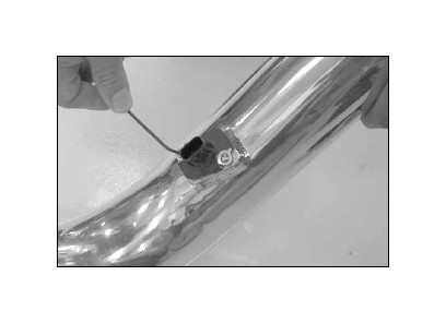
17a. On vehicles equipped with the brake booster vent line install the K&N® intake tube into the silicone hose at the throttle body. Align the brake booster vent line to the K&N® intake tube as shown and place a mark for drilling location.
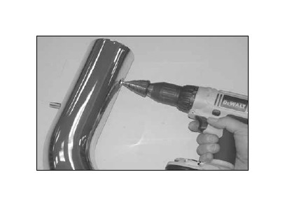
17b. Remove the intake tube and drill a 5/8” hole at the location marked in step #17a.
NOTE: Be sure to remove all the burrs after drilling.
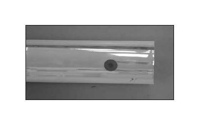
17c. Install the provided grommet into the K&N® intake tube as shown.
18. Install the mass air sensor into the K&N® Intake tube and secure with the provided hardware as shown.
19. Install the silicone hose and hose clamps onto the K&N® intake tube as shown.
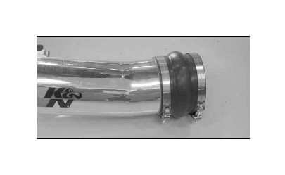
20. Slide the silicone hump hose onto the filter adapter, then, slide the other end into the 90° silicone hose, adjust everything for best fit and clearance and tighten all hose clamps as shown.
21. Adjust the heat shield for best fit and clearance, then, tighten all hardware at this time.
22. Remove the stock crankcase vent hard line as shown.
23. Install the provided silicone hose onto the vent on the cam cover, then, connect the other end to the vent on the K&N® intake tube as shown.
23a. On vehicles equipped with brake booster vent lineInstall the provided hose mender into the grommet in the intake tube and connect the brake booster vent line to the hose mender.
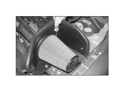
24. Install the K&N® air filter and tighten the provided hose clamp as shown.
25. Reconnect the mass air sensor electrical connection as shown.
26. Reconnect the vehicle’s negative battery cable. Double check to make sure everything is tight and properly positioned before starting the vehicle.
27. The C.A.R.B. exemption sticker, (attached), must be visible under the hood so that an emissions inspector can see it when the vehicle is required to be tested for emissions. California requires testing every two years, other states may vary.
28. It will be necessary for all K&N® high flow intake systems to be checked periodically for realignment, clearance and tightening of all connections. Failure to follow the above instructions or proper maintenance may void warranty.
ROAD TESTING:
1. Start the engine with the transmission in neutral or park, and the parking brake engaged. Listen for air leaks or odd noises. For air leaks secure hoses and connections. For odd noises, find cause and repair before proceeding. This kit will function identically to the factory system except for being louder and much more responsive.
2. Test drive the vehicle. Listen for odd noises or rattles and fix as necessary.
3. If road test is fine, you can now enjoy the added power and performance from your kit.
4. K&N Engineering, Inc., suggests checking the air filter element periodically for excessive dirt buildup. When the element becomes covered in dirt (or once a year), service it according to the instructions on the Recharger® service kit, part number 99-5050 or 99-5000.
