 FREE 1 to 3-Day Delivery on Orders $119+ Details
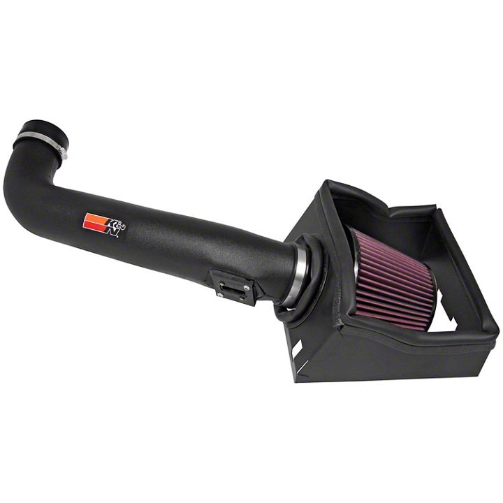
How to Install K&N Series 57 FIPK Cold Air Intake on your F-150
Installation Time
1 hours
Tools Required
- Flat blade Screwdriver
- Ratchet
- Extension
- 8mm Socket
- 10mm Socket
- 13mm Socket
- 10mm Wrench
- T20 Torx Wrench
- 2.5mm Allen Wrench
- 4mm Allen Wrench
Shop Parts in this Guide
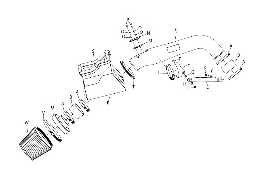
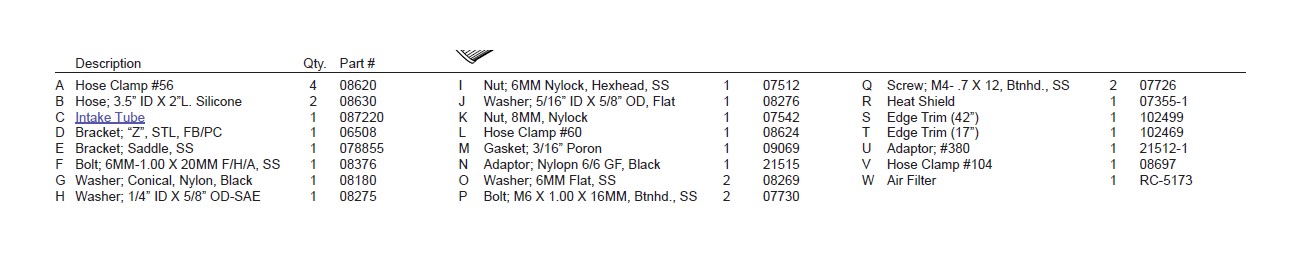
PARTS LIST:
NOTE: FAILURE TO FOLLOW INSTALLATION INSTRUCTIONS AND NOT USING THE PROVIDED HARDWARE MAY DAMAGE THE INTAKE TUBE, THROTTLE BODY, AND ENGINE.
TO START:
1.Turn off the ignition and disconnect the negativebattery cable.
NOTE: Disconnecting the negative battery cable erases pre-programmed electronic memories. Write down all memory settings before disconnecting the negative battery cable. Some radios will require an anti-theft code to be entered after the battery is reconnected. The anti-theft code is typically supplied with your owner’s manual. In the event your vehicles’ anti-theft code cannot be recovered, contact an authorized dealership to obtain your vehicles anti-theft code.
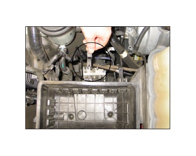
2.Release the red locking tab and disconnect themass air sensor electrical connection.
3.Remove the two bolts that secure the enginecover.
NOTE: Some vehicles may not be equipped with an engine cover.
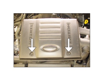
4.Remove the engine cover as shown.
NOTE: Some vehicles may not be equipped with an engine cover.
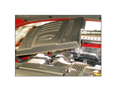
5.On the factory inlet tube, loosen the hose clampsat the upper air box housing and at the throttle body inlet.

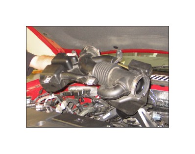
6.Remove the factory inlet tube as shown.
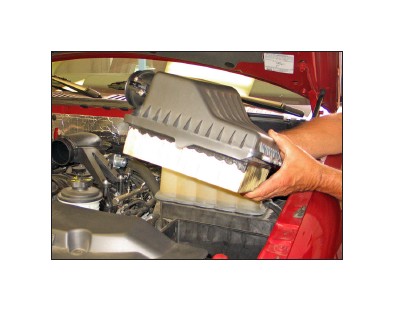
7.Un-snap the three latches securing the upper airbox housing to the lower air box housing as shown.
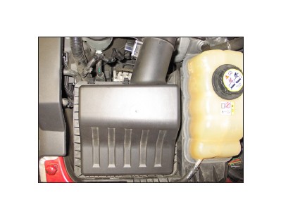
8.Remove the upper air box housing and air filterfrom the lower air box housing as shown.
NOTE: K&N Engineering, Inc., recommends that customers do not discard factory air intake.
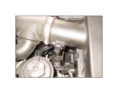
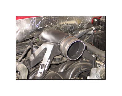
9.Install silicone hose (#08630) onto the throttlebody inlet tube with the provided hose clamps as shown.
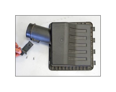
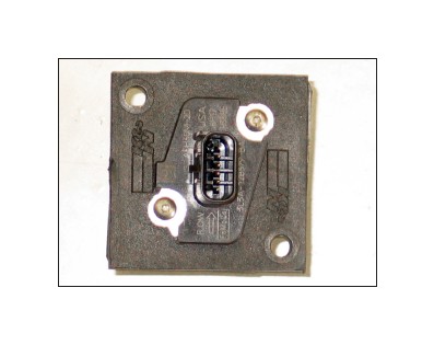
10.Remove the two screws securing the mass airsensor, then remove the mass air sensor from the upper air box housing as shown.
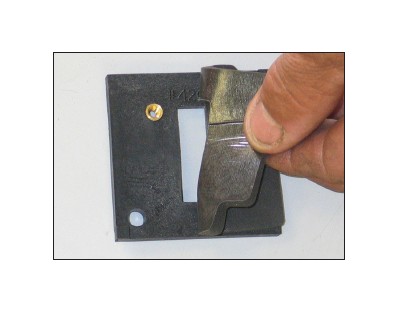
11.Install the provided gasket onto the mass airadapter as shown with the sticky side down.
12. Install the mass air sensor onto the mass air sensor adapter with the provided hardware as shown.
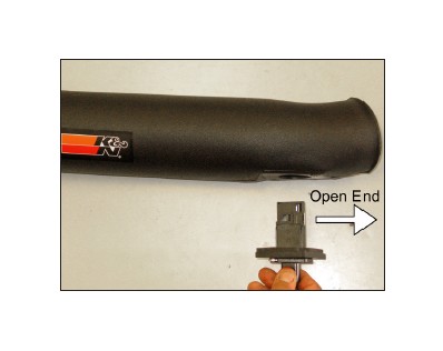
13. Install the mass air sensor assembly into the intake tube.
NOTE: Verify the open end of the mass air sensor is facing toward the “air filter end” of the intake tube.
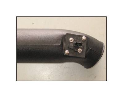
14. Secure the mass air sensor assembly onto the intake tube with the provided hardware as shown.
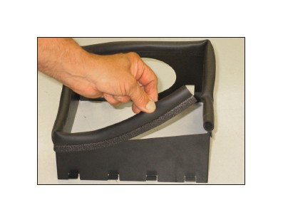
15. Install the long edge trim onto the heat shield as shown.
NOTE: Some trimming of the edge trim may be necessary.
16. Install the short edge trim into the hole in the heat shield as shown.
NOTE: Some trimming of the edge trim may be necessary.
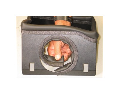
17. Remove the center latch from the lower air box as shown.
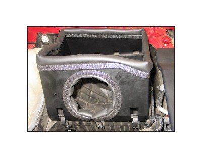
18. Install the heat shield and secure with the two remaining latches as shown.
NOTE: A gap is normal between the lower air box and heat shield on the clip side of the heat shield.
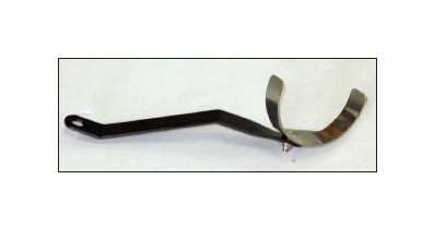
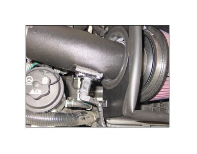
19. Install the saddle clamp onto the tube bracket (#06508) and secure with the provided hardware.
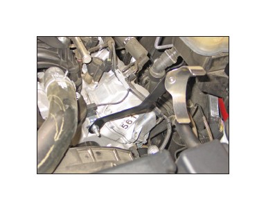
20. Install the tube bracket assembly onto the timing cover stud at the front of the engine as shown.
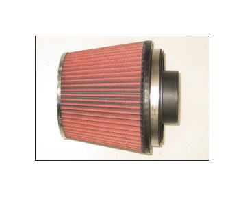
21. Install the air filter adapter into the K&N® air filter and secure with the provided hose clamp as shown.
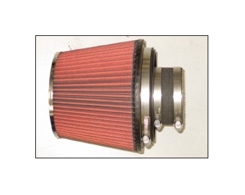
22. Install silicone hose (#08630) onto the air filter adapter and secure with the provided hose clamp.
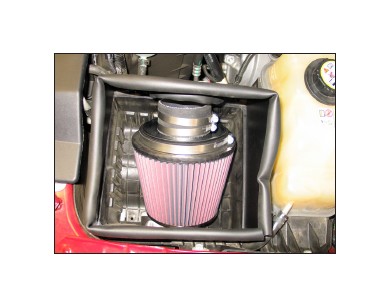
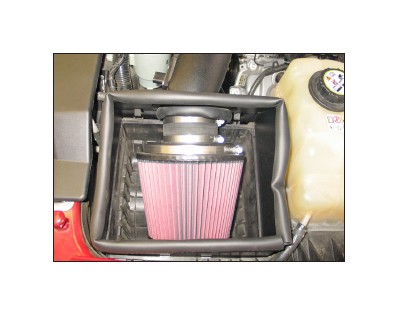
23. Place the air filter assembly into the heat shield as shown.
24. Install the intake tube into the air filter assembly and silicone hose at the engine inlet tube, then align with the tube bracket and secure with the provided hose clamps as shown.
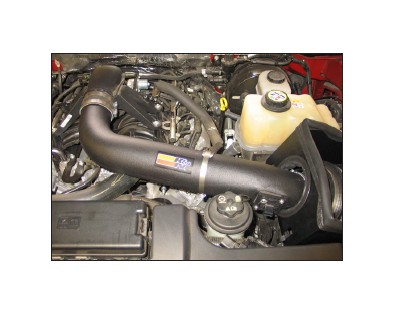
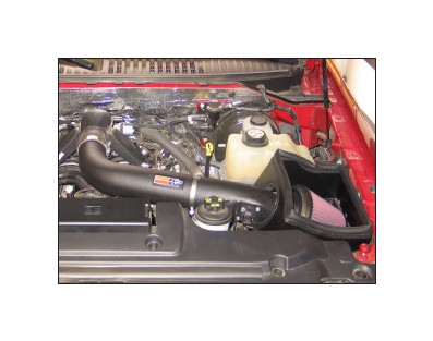
25. Secure the K&N® air filter assembly onto the K&N® intake tube with the provided hose clamp as shown.
26. Re-connect the mass air sensor electrical connection as shown.
27. Re-connect the vehicle’s negative batter cable. Ensure everything is tight and properly positioned before starting the vehicle.
28. The C.A.R.B. exemption sticker, (attached), must be visible under the hood so that an emissions inspector can see it when the vehicle is required to be tested for emissions. California requires testing every two years, other states may vary.
29. It will be necessary for all K&N® high flow intake systems to be checked periodically for alignment, clearance, and tightening of all connections. Failure to follow above the above instructions, and/or improper maintenance may void warranty.
ROAD TESTING:
1. Start the engine with the transmission in neutral or park, and the parking brake engaged. Listen for air leaks or odd noises. For air leaks secure hoses and connections. For odd noises, find cause and repair before proceeding. This kit will function identically to the factory system except for being louder and much more responsive.
2. Test drive the vehicle. Listen for odd noises or rattles and fix as necessary.
3. If road test is fine, you can now enjoy the added power and performance from your kit.
4. K&N Engineering, Inc., requires cleaning the intake system’s air filter element every 100,000 miles. When used in dusty or off-road environments, our filters will require cleaning more often. We recommend that you visually inspect your filter once every 25,000 miles to determine if the screen is still visible. When the screen is no longer visible some place on the filter element, it is time to clean it. To clean and re-oil, purchase our filter Recharger® service kit, part number 99-5050 or 99-5000 and follow the easy instructions.
