 FREE 1 to 3-Day Delivery on Orders $119+ Details
How to Install ReadyLIFT 7 in. Off Road Lift Kit w/ SST3000 Shocks - Silver on your F-150
Please read Instructions thoroughly and completely before beginning installation.
Installation by a certified mechanic is recommended.
ReadyLIFT® Off Road Suspension is NOT responsible for any damage or
failure resulting from improper installation.
Safety Warning: Suspension systems or components that enhance the on and off-road performance of your vehicle may cause it to handle differently than it did from the factory. Extreme care must be used to prevent loss of control or vehicle rollover during abrupt maneuvers. Always operate your vehicle at reduced speeds to ensure your ability to control your vehicle under all driving conditions. Failure to drive safely may result in serious injury or death to driver and passengers. Driver and passengers must ALWAYS wear your seat belts, avoid quick sharp turns and other sudden maneuvers. ReadyLIFT® Off Road Suspension does not recommend the combined use of suspension lifts, body lifts, or other lifting devices. You should never operate your vehicle under the influence of alcohol or drugs. Constant maintenance is required to keep your vehicle safe. Thoroughly inspect your vehicle before and after every off-road use. It is the responsibility of the retailer and/or the installer to review all state and local laws, with the end user of this product, related to bumper height laws and the lifting of their vehicle before the purchase and installation of any ReadyLIFT® products. It is the responsibility of the driver/s to check their surrounding area for obstructions, people, and animals before moving the vehicle. All raised vehicles have increased blind spots and damage, injury and/or death can occur if these instructions are not followed.
Installation Warning: All steps and procedures described in these instructions were performed while the vehicle was properly supported on a two post vehicle lift with safety jacks. Use caution during all disassembly and assembly steps to insure suspension components are not over extended causing damage to any vehicle components and parts included in this kit. Included instructions are guidelines only for recommended procedures and are not meant to be definitive. Installer is responsible to insure a safe and controllable vehicle after performing modifications.
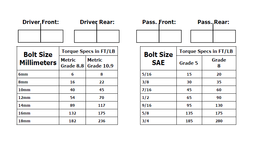
ReadyLIFT® Off Road Suspension recommends the use of an OE Service Manual for model/year of vehicle when disassembly and assembly of factory and related components. Unless otherwise specified, tighten all bolts and fasteners to standard torque specifications listed within the OE Service Manual, or as referenced in the torque specification list provided in these instructions.
Suspension components that use rubber or urethane bushings should be tightened with the vehicle at normal ride height. This will prevent premature wear or failure of the bushing and maintain ride comfort. Larger tire and wheel combinations may increase leverage on suspension, steering, and related components. Due to payload options and initial ride height variances, the amount of lift is a base figure. Final ride height dimensions may vary in accordance to original vehicle ride height. Always measure the vehicle ride height prior to beginning installation.
Vehicle ride height chart
Bill of Materials
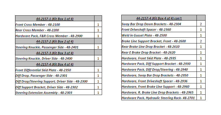
The Bill of Materials represents the component contents of this kit. All hardware is of the highest grade and the components are manufactured to exacting specifications for a trouble free installation. Use the attached torque specifications chart when final tightening of the nut and bolts are done.
Safety Warning
Before you start installation:
ReadyLIFT® Off Road Suspension highly recommends that the installation of this product be performed by a professional mechanic with experience working on and installing suspension products. Professional knowledge and skill will typically yield the best installation results. If you need an installer in your area, please contact ReadyLIFT® Suspension customer service to find one of our “Pro‐Grade” Dealers.
Notes:
Installation by a professional mechanic is highly recommended.
A Factory Ford Service Manual for your specific Year / Make / Model is highly recommended for reference during installation.
Installation requires cutting and welding of the vehicle frame.
Vehicles with a two piece rear driveline may require a carrier bearing drop support bracket, call technical assistance for details.
Vehicles achieving more than 5” of rear lift may require rear driveline modifications, call technical assistance for details.
All lifted vehicles may require additional driveline modifications and or balancing.
A four wheel vehicle alignment will need to be performed after installation of this product.
Speedometer / Computer recalibration is required if changing /‐ 10% from factory tire diameter.
Use of a Vehicle Hoist will greatly reduce installation time. Vehicle must be in excellent operating condition.
Repair or replace any and all worn or damaged components prior to installation.
Front Disassembly:
***Important*** Check kit contents with Bill of Materials to ensure that all parts are included prior to starting installation. Kit components and hardware are of high grade and specification, do not substitute or modify components or hardware. Contact ReadyLIFT Suspension customer service with any questions that you may have. ***Important*** Read and study this manual prior to installation, and familiarize yourself with the kit components and procedures. If you are not confident in your abilities or tools, do not perform the installation and refer to one of our Pro‐Grade Installers. This is a permanent installation and requires cutting of the frame. NOTE: These instructions are for trucks equipped with an electronic steering rack. For trucks with a hydraulic steering rack please see the supplemental instructions in Hardware Pack 48‐2701.
1. Park the vehicle on a clean, flat surface and block the rear wheels for safety. Engage parking brake.
2. Record stock vehicle ride height measurements on both the front and the rear, this will provide and guideline on vehicle rake and lift height. Measure from the center of the wheel up to the bottom edge of the fender well opening and record on chart provided on page 2.
3. Disconnect the vehicle power source at the ground terminal on the battery. ***2011 and newer models equipped with EPAS (Electronic Power Assist Steering), disconnect the power steering control module connector to avoid arching of the contacts in the internal power relay from a hammer blow or impact wrench.
4. You must Lock Steering Wheel in straight forward position with the column lock or steering wheel locking device. ***Rotating the steering wheel while disconnected from the vehicle rack & pinion WILL cause damage to the steering column and / or internal clock spring.
5. Raise the front of the vehicle and support with jack stands at each frame rail behind the lower control arms.
6. Remove the front wheels.
7. Remove all factory skid plates and hardware (including the nut‐serts in the frame).
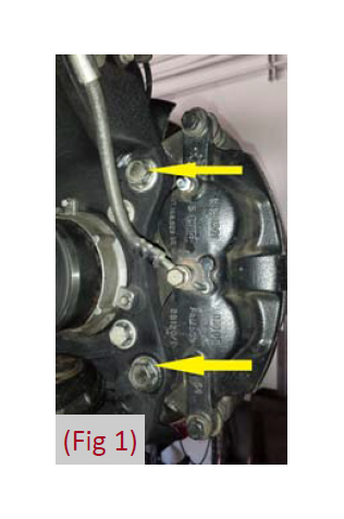
8. Remove the brake caliper anchor bracket bolts and remove the caliper from the knuckle (Fig 1). Hang the caliper out of the way using a S‐Hook or suitable strap. “Do Not” let the caliper hang by the brake hose.
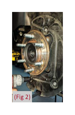
9. Remove the brake rotor and dust shield, set aside. (Fig 2) ***Note – Mark all components to their corresponding side of removal (driver / passenger) in order to aid re‐installation.
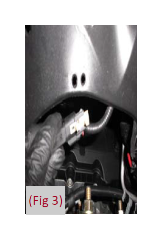
10. Disconnect the ABS and hub vacuum lines from the retaining clips. Disconnect the brake line bracket from the frame rail. Disconnect the ABS line from the inner fender well, and disconnect the clip. (Fig 3)
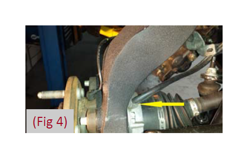
11. Disconnect hub vacuum line from the hub. (Fig 4)
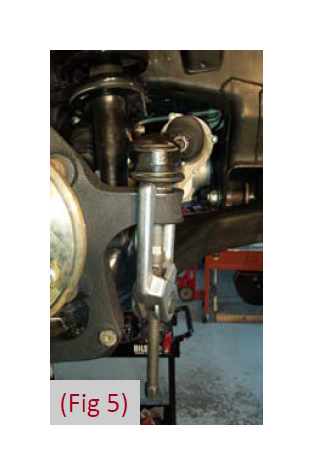
12. Disconnect the tie rod ends from the steering knuckles (Fig 5). Remove and retain the mounting nuts. Utilizing a ball joint pulling tool or suitable device, disconnect the tie rod end from the steering knuckle. Take care not to strike the tie rod end.
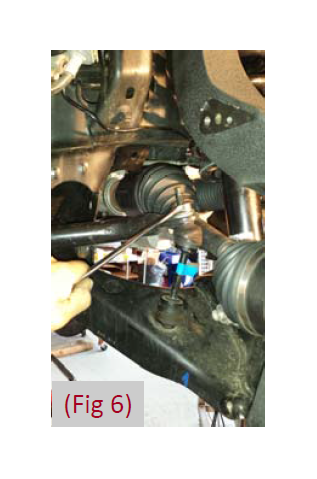
13. Disconnect the sway bar links from the sway bar (Fig 6). Retain hardware. The sway bar links do not need to be removed from the lower control arms.
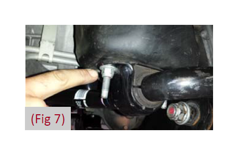
14. Remove the four sway bar mounting nuts and remove the sway bar from the vehicle. (Fig 7) Retain hardware
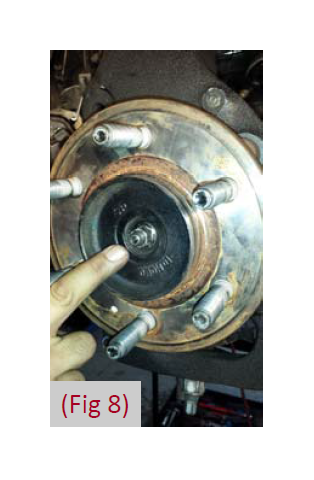
15. Carefully remove the hub dust cap to expose the axle shaft nut (Fig 8) . Remove the axle shaft nut. Retain the cap and nut, they will be reinstalled later.
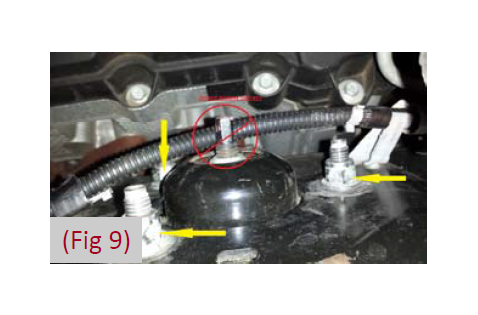
16. Loosen but do not remove the three strut assembly mounting nuts at the frame (Fig 9).
***Warning*** Do not attempt to loosen or remove the middle strut nut (shock shaft mount) from the mounting plate, the strut / spring assembly is under high pressure and serious damage or injury can occur.
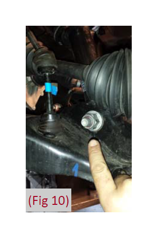
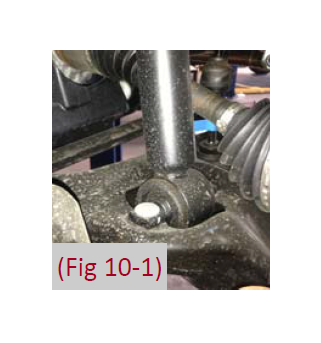
17. Loosen and remove the nut from the strut‐to‐lower control arm mounting bolt (Fig 10) . Leave the bolt in place at this time. Retain the mounting nut. For 2014‐up see Fig 10‐1.
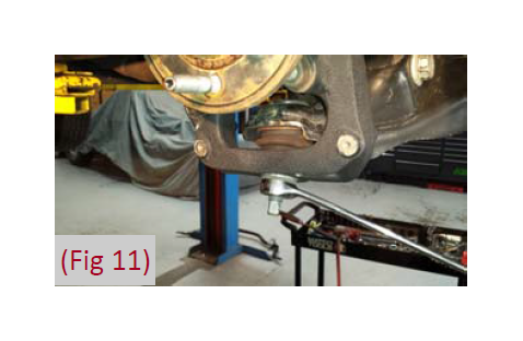
18. Remove the upper and lower ball joint nuts (Fig 11) and reinstall a few turns.
19. Utilizing a Ball Joint Pulling Tool or suitable device, separate the knuckle from the upper and lower ball joints to dislodge the joints from the knuckle.*** Vacuum Hubs are Delicate and easily Damaged. Use Extra Caution.***
20. Remove the upper ball joint and the strut‐to‐lower control arm bolt. Swing the knuckle/lower control arm down to remove the CV shaft from the hub. Retain ball joint nut and strut bolt.
21. Remove the lower ball joint nut and remove the knuckle from the vehicle. Retain hardware.
22. Remove the lower control arm mounting bolts and remove the lower control arms from the chassis. Retain hardware.
23. Remove the three strut assembly mounting nuts at the frame and remove the strut assembly from the vehicle. (Fig 9)
24. Mark the struts to distinguish between driver and passenger side.
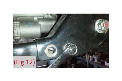
25. Remove the four bolts that attach the OE rear crossmember (Fig 12) to the frame and remove the crossmember from the vehicle. It may be necessary to clean the bolts of excess OE frame paint coating. Discard the crossmember, but retain the hardware for re‐installation.
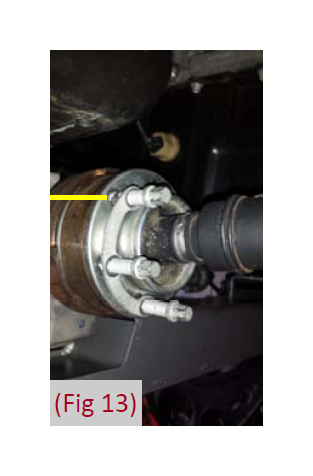
26. Remove the driveshaft mounting bolts, mark and disconnect the driveshaft from the differential. (Fig 13) Allow the driveshaft to rest out of the way.
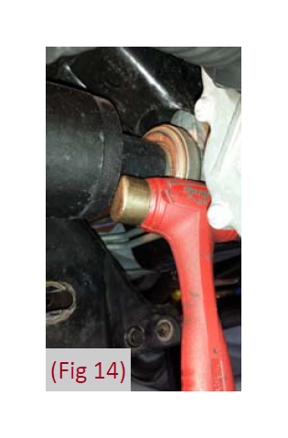
27. Remove both the driver side and passenger side CV axle. Strike the shaft with a mallet or soft hammer to dislodge it from the splines. This will make handling the differential much easier. (Fig 14) ***Warning*** The front differential is heavy and awkward. It is best removed by two people. Do not tilt the differential towards the opening on the driver side as gear oil will spill out.
28. Remove the front differential. Utilizing an appropriate jack, support the differential housing. Loosen all of the hardware and move the differential to the passenger’s side as far as possible. Orientate the joint at the steering rack so there is the most possible clearance to remove the front
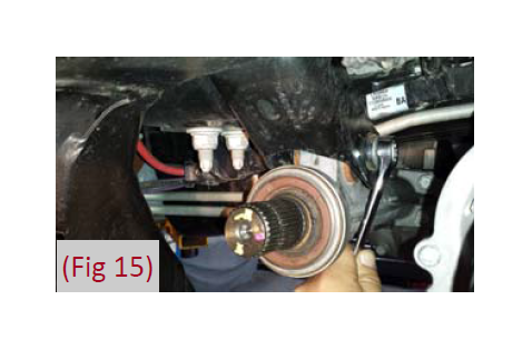
(28. Cont) driver’s side bolt. Remove this bolt first. Disconnect the breather hose from the differential housing (an extension will be added). Remove the rear driver’s side and one passenger’s side differential mounting bolts (Fig 15) and remove the differential from the vehicle.
29. 2009‐13 pull down on the differential breather hose to gain additional slack needed when reinstalling the differential. 2014‐up ‐ Install 3” tube with male‐male barb.
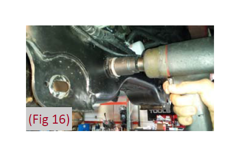
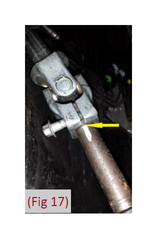
30. Locate the rack & pinion coupler pinch bolt. Mark the alignment of the rack and pinion input shaft and the coupler. (Fig 16) Remove the pinch bolt and separate. Disconnect Electrical connections before removing Rack and Pinion. Locate the two large bolts that hold the rack & pinion to the vehicle frame and remove. (Fig 17) Remove the rack & pinion assembly from the vehicle. Note: 2009 to 2010 Vehicles equipped with hydraulic steering will need to disconnect the hydraulic hoses at the steering rack for removal. Check for supplemental instructions for the 09‐10 F150.
***Warning*** Special care must be taken in handling the rack & pinion unit to prevent damage. Vehicles equipped with EPAS (Electronic Power Assist Steering) , should safely stow the rack and pinion unit in a safe place to avoid damage. Do not drop or strike the rack and pinion unit.
Front Installation
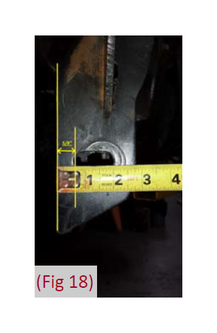
32. The driver’s side rear lower control arm frame pocket must be modified to provide clearance for the differential in its relocated position. On the front side of the frame pocket measure from the inside edge of the slot 5/8”. (Fig 18) Mark a vertical cut line at the mark, all the way to the bottom.
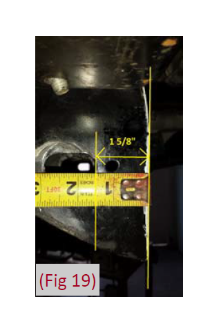
33. On the back side of the frame pocket, measure from the inside edge of the slot 1‐5/8” and mark. (Fig 19) Mark a vertical cut line at the mark, all the way to the bottom
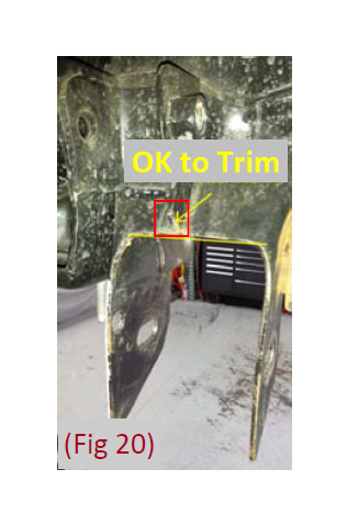
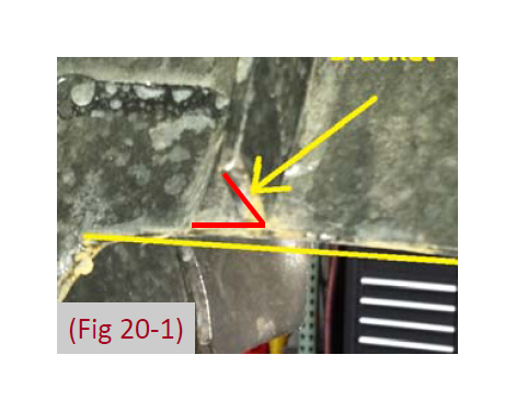
34. Over the top of the pocket, connect the front cut line straight to the back cut line. This will require cutting through the factory differential mount tab. (Fig 20)
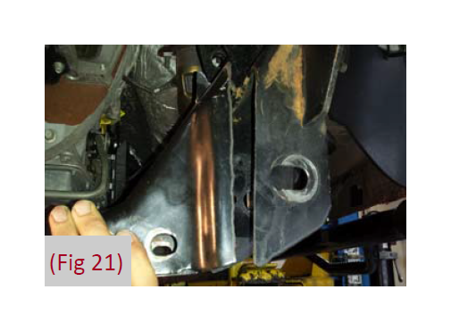
35. Using a suitable cutting device, trim the shown area from the vehicle. (Fig21) Round off the bottom corners and sand any sharp edges.
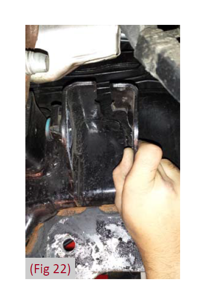
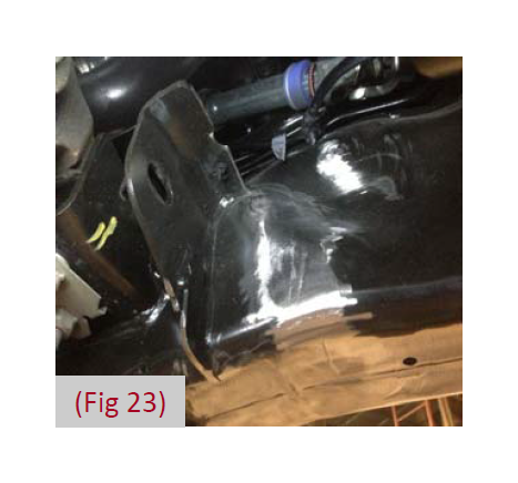
36. The factory front driver side differential mounting tab must also be removed (Fig 22, 23) completely. Remove a minimum the front half of this tab and grind flush to the frame.
37. Clean and paint all bare metal surfaces utilizing a premium paint to prevent corrosion.
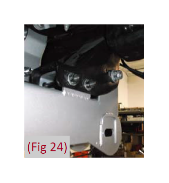
38. Install the rear crossmember (#48‐ 2200) and check the driver and passenger frame pockets for necessary clearance. A small amount of material may need to be removed. (Fig24)
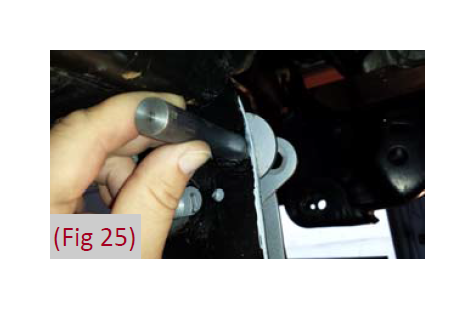
39. With the crossmember installed mark the differential hole on the factory control arm pocket (Fig 25). Remove the crossmember and drill a 9/16” hole at the mark, for easiest access drill the hole from front to back, a step drill is recommended for this step. Re‐install the rear crossmember to ensure alignment and clearance of all holes and fitment on the driver and passenger sides. Remove rear crossmember at this time and set aside.
40. Steering Extension Pre‐Assembly – This system is equipped with a patent pending rack & pinion steering extension kit. Please follow installation instructions closely and check for all clearances and tolerances along the way.
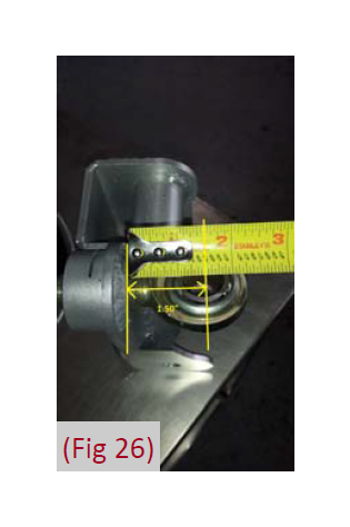
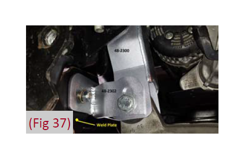
40a. Find the driver side differential drop bracket (#48‐2300) with steering support bracket. Clean/ chase all threads then install ¾” rod end into the pinch bung as shown. Set the ¾” rod end at approximately 1.50” from the bracket face to center of the ball. (Fig 26) Install the 1/4”‐20 allen bolt into the pinch bung as shown do not tighten at this time.
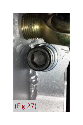
40b. Install Driver Side (#48‐2300 and #49‐2940) differential drop bracket assembly into the frame using supplied 14mm x 90mm allen head cap screw and utilizing the Factory Slide nut on Frame, do not tighten (Fig 27).
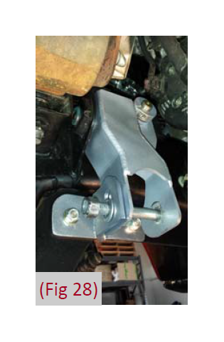
40c. Find the T shaped (#48‐ 2302) Differential and Steering Support Bracket and the Weld in Frame Plate (#48‐2500) and loosely attach to the differential drop bracket assembly (Fig. 28).
40d. Locate the steering u‐joint (#48‐2303‐2) and steering extension shaft (#48‐2303‐1).
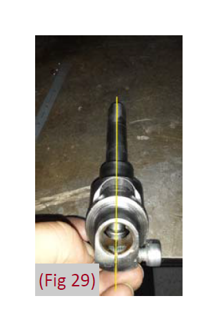
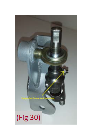
40d. (continued) It is important that the male flats on the extension shaft are oriented perfectly with the female flats on the u‐joint. (Fig. 29) Insert the splined shaft into the u‐joint and secure with the supplied set screw (Loctite) and jamb nut as shown and torque to 165‐183 in‐lbs. (Fig 30) Set assembly aside for now.
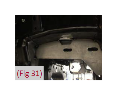
41. Remove the paint from the driver’s side rear control arm pocket. Place the weld in plate so that it is aligned with the outside edge of the bracket and the plate is vertical. Note: Newer models will require the factory mount that wraps to the bottom side of the frame to be trimmed for clearance. Tack weld in place. (Fig 31)
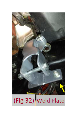
42. Temporarily install the differential drop bracket (#48‐2300) on the driver’s side with supplied 14mm x 90mm Allen bolt, flat washer, and lock washer. Place the driver’s side differential support bracket (T shaped bracket #48‐2302) up between the weld in plate (48‐2500) and differential drop, do not tighten at this time. (Fig 32)
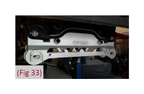
43. Install the front crossmember (#48‐ 2100) using the OE hardware, do not tighten at this time. (Fig. 33) Note: The front crossmember is designed to fit snugly against the frame. In some cases it may be necessary to remove a small amount of material from the frame pocket and or the crossmember.
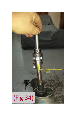
44. Install steering extension assembly (#48‐2303) to rack & pinion unit. It is important that the male flats on the extension shaft are oriented perfectly with the female flats on the rack & pinion input shaft. (Fig. 34)
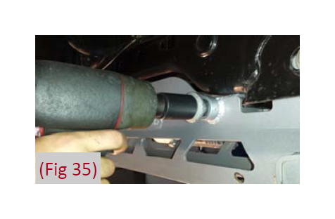
45. Install rack & pinion onto front cross member, during this procedure, it will be necessary to guide the steering extension shaft through the ¾” rod end on the steering and differential support bracket. (Fig 35) It may be helpful to have two people.
45a. Refer to the supplemental instructions included in Hardware Pack# 48‐2701 if your vehicle is equipped with hydraulic power steering. Ensure that the lines do not rub on any surfaces.
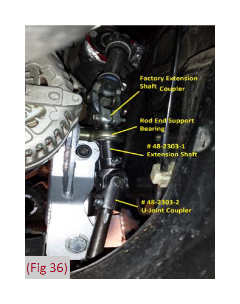
46. Accessing the steering extension assembly through the front of the frame (on top of the crossmember), (Fig 36) attach the factory steering coupler to the top of the extension shaft. It may be necessary to loosen the rack and pinion on the driver side to slightly lower the unit to allow engagement of the assembly. Apply Loctite Tighten all steering extension hardware at this time.
Factory steering u‐joint pinch bolt to extension shaft – 165‐183 in‐lbs.
¾” Rod end pinch bung (1/4‐20 x ¾” allen bolt) – 93‐129 in‐lbs.
Supplied 5/16” steering extension assembly ujoint pinch bolt – 165‐183 in‐lbs.
47. At this point of the installation, it is necessary to check all steering components for adequate clearance and movement. If there is any bind or clearance issues, address them at this time. *** Turn the steering wheel full left—>full right multiple times to ensure smooth rotation.*** There is adjustment of the rod end from side to side and sanding on the frame that can gain additional clearance if needed. Adjustments made later in the install are difficult due to limited access to the steering extension.
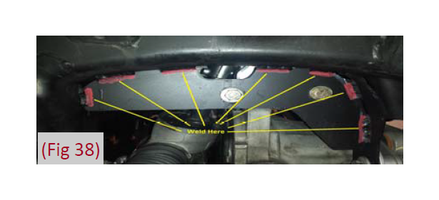
48. Ensure that the steering extension support bracket, the T‐shaped support bracket, and the weld plate on the frame all line up properly. (Fig 37) If the slots align, remove the T‐shaped support bracket and weld the outside of the weld plate in the places shown. (Fig 38)
49. Allow the metal to cool, clean all welded surfaces and apply several coats of premium paint for protection.
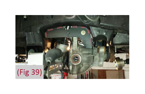
50. Attach the passenger side differential relocation bracket (#48‐2301) to the frame with OE hardware, do not tighten at this time. Raise the differential into the brackets attached into the vehicle by aligning the differential mounts in the two front drop brackets and attach with supplied 14mm x 100mm hex head bolts hardware, do not tighten at this time. (Fig 39)
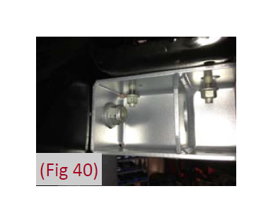
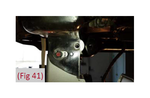
51. Install the new rear crossmember (#48‐2200) in the rear lower control arm frame pockets. Attach the rear crossmember with the sway bar drop brackets with existing OE hardware, do not tighten. (Fig 40) Ensure the hole that was drilled in the frame pocket lines up to the differential mounting hole in the bracket. (Fig 41) Do not tighten hardware at this time.
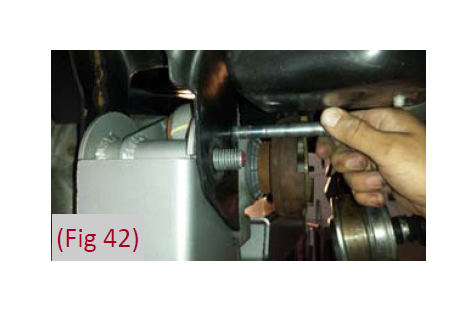
52. Fasten the differential to the rear crossmember (Fig 42) with the supplied 14mm x 100mm bolt, washers, and nut. Run the bolt from front to rear. Leave hardware loose.
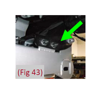
53. Install the OE hardware through the existing frame and into new passenger side crossmember frame support. Leave hardware loose (Fig 43).
54. Torque all of the differential mounting hardware to 95 ft‐lbs. Attach the differential breather tube. 2014‐up ‐ Install 3” tube with male‐male barb.
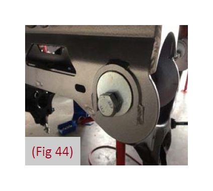
55. Install the lower control arms into the new cross members utilizing the provided 18mm cam eccentric bolts, cam eccentric washers and 18mm nuts. Run the front crossmember cam eccentric bolts starting at the front and pointing to the rear, leave loose. Run the rear cross member cam eccentric bolts starting at the rear pointing to the front. The main body of the cam eccentric washers should be pointed ‘up’ in the cam slots. (Fig 44)
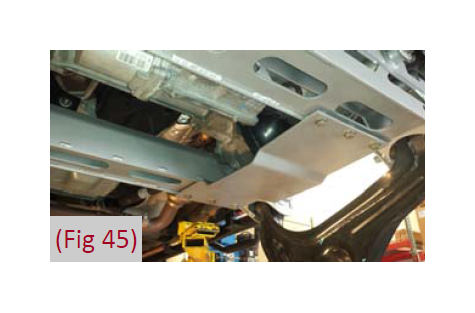
56. Install the provided differential skid plate (#48‐2350) to the front and rear cross members with 3/8” x 1‐1/4” button head bolts and 3/8” SAE washers into the weld nuts in the cross members. (Fig 45) Leave hardware loose.
57. With the lower control arms installed, apply Loctite to, and torque the four crossmember mounting bolts to 222 ft‐lbs. Ensure that the front and rear cross members along with the differential are centered in the vehicle chassis. Torque the differential skid plate bolts to 35 ft‐lbs. Tighten sway bar drop hardware to 60 ft‐lbs.
58. Reinstall the driver side and passengers side CV axles.
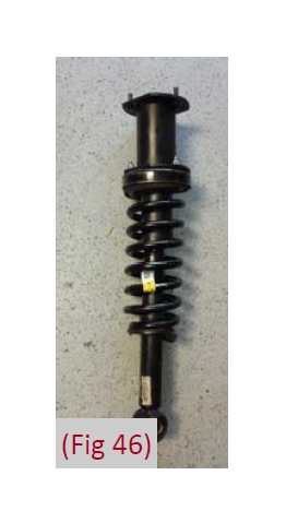
59. Obtain the appropriate MLS upper strut spacers and match the driver side spacer to the driver side strut and the passenger side spacer to the passenger strut. Install the spacer to the strut utilizing OE hardware and torque to 30 ft‐lbs. (Fig 46)
60. Install the strut assemblies in the appropriate sides on the vehicle with the supplied hardware, leave hardware loose at this time.
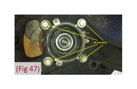
61. Remove the four hub bolts from the stock steering knuckle and remove the hub from the knuckle. (Fig 47) Inspect the mounting surface of the hub assembly and clean any dirt or corrosion off as necessary.
62. Install the hub into the corresponding new ReadyLIFT steering knuckle (driver #48‐2400 , passenger #48‐2401) and fasten with the previously removed OE bolts. The ABS wire mounting location will be located at the ‘top’ of the hub. Use Loctite on the bolt threads and torque to 148 ft‐lbs.
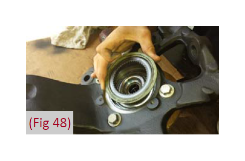
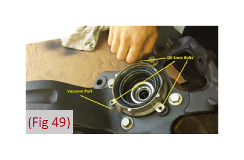
63. Remove the three 6mm bolts mounting the vacuum hub assembly to the inside of the OE knuckle. Transfer the vacuum assembly over to the new knuckle. Make sure the vacuum line attachment port is pointing towards the top. Attach with the previously removed OE bolts and tighten bolts securely to about 5‐7 ft‐lbs. (Fig 48, 49)
64. Install the new knuckle assembly on the lower control arm ball joint and loosely fasten with the original nut. Install the CV axle shaft in the hub, swing the whole assembly up and attach the lower control arm to the strut with the original hardware. Leave all hardware loose.
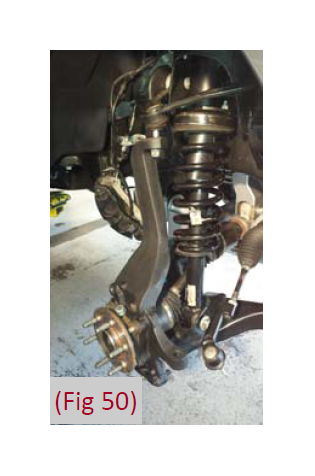
65. Attach the upper control arm to the knuckle with the original nut. Torque the upper ball joint to 85 ft‐lbs and the lower ball joint to 111 ft‐lbs. (Fig 50)
66. Torque the upper strut nuts to 35 ft‐lbs. Do not tighten the lower bolt at this time, it will be tightened after the vehicle is put back on the ground with the weight of the vehicle on the suspension.
67. Fasten the CV axle shaft to the hub with the original nut. Make sure the vacuum actuator splines are engaged properly on the axle and hub assembly. The hub should have a very minor amount of rotational play with the CV axle shaft if installed properly, torque to 20 ft‐lbs and reinstall the dust cap.
68. Install the steering tie rod to the steering knuckle and torque to 111 ft‐lbs.
69. Install the ABS cable to the top of the hub assembly utilizing previously removed OE hardware and torque to about 5‐7 ft‐lbs.
70. Install the dust shield with the factory 6mm bolts and tighten the bolts securely to about 5‐7 ft‐lbs.
71. Install the brake rotor and caliper to the hub assembly and ReadyLIFT knuckle with OE bolts and torque to 148 ft‐lbs.
72. Install the brake line relocation brackets (#48‐2600) at the frame. Attach with OE hardware to frame, attach brake line retaining clip with 5/16” bolt, nut, and washer to the relocation bracket. Tighten to 20 ft‐lbs.
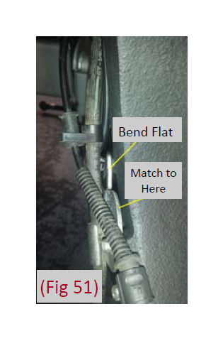
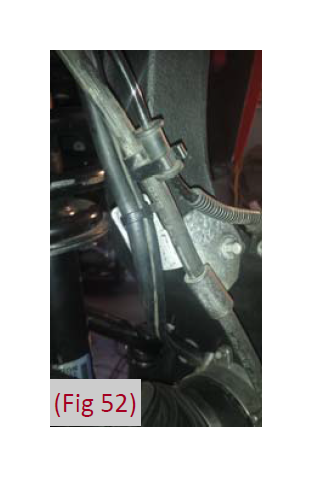
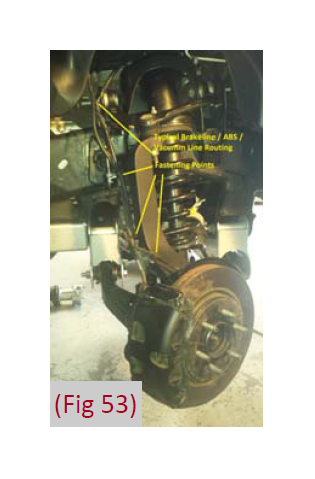
73. Attach the ABS line to the connector at the inner fender and the vacuum line to the hub. Route the lines similar to the factory setup down to the side of the knuckle. Attach the ABS wire with the factory 6mm bolt to the side of the knuckle. Utilizing OE hardware, attach the brake line to the side of the new steering knuckle, the brake line locating tab will go into the unthreaded hole. It will be necessary to bend the back side 90 degree tab so that it is straight with the rest of the bracket (flatten the bracket). (Fig 51, 52) It may be necessary to use some zip ties or appropriate fasteners to link the different lines securely together up the knuckle. (Fig 53) Cycle the steering and check for adequate clearance.
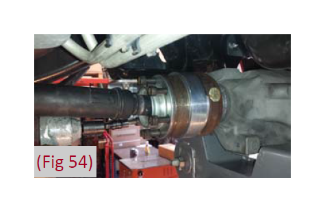
74. Install the supplied driveshaft spacer and reattach the front driveshaft to differential with the supplied new hardware and torque bolts to 76 ft‐lbs. (Fig 54)
75. Install the sway bar to the new sway bar drop brackets with supplied 7/16” x 1‐1/4” bolts, nuts and 7/16” SAE washers. Attach the sway bar to the sway bar end links on the lower control arms utilizing the original hardware and torque to 45 ftlbs. Torque the 7/16” hardware to 45 ft‐lbs.
76. Install the wheels and tires and lower the vehicle to the ground.
77. Jounce the front and rear of the vehicle to settle in the suspension. Torque the lower strut mount bolt to 350 ft‐lbs (2009‐2013). Center the lower control arm cam eccentrics in their slotted holes and torque to 150 ft‐lbs.
78. Re‐check that all hardware is tight and of proper torque value prior to vehicle operation.
79. If driving the vehicle to an alignment shop, adjust the toe prior to vehicle operation.
Rear Installation:
80. Block the front wheels and raise the rear of the vehicle. Place jack stands under the frame rails ahead of the spring hangers.
81. Remove the wheels.
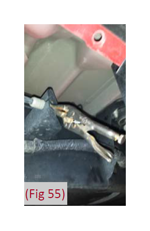
82. The parking brake cable must be relocated. To disconnect the cable from the frame first pull down on the cable and clamp it off with vise grips near the middle of the frame. (Fig 55 ) This will gain slack to disconnect the driver’s side rear cable from the main (passenger’s side) cable.
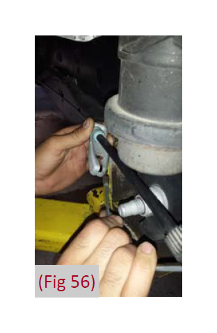
83. Remove the driver’s side parking brake cable from the junction bracket. (Fig 56)
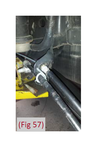
84. Compress the retaining tabs on the driver side cable and remove it from the spring hanger. (Fig 57) It will be relocated and reconnected in a later step.
85. Disconnect the rear brake line bracket from the inner frame rail.
86. Support the rear axle with a hydraulic jack and remove the OE shocks. Retain mounting hardware for later use. Note: It is best to perform the rear installation on one side at a time.
87. Remove the passenger’s side u‐bolts and discard, they will not be reused.
88. Lower the axle and remove the OE lift block and discard, it will not be reused.
89. If installing an optional add‐a‐leaf to the spring pack, perform this procedure at this time by following the instructions included with your add‐a‐leaf kit. If you are not installing an add‐a‐leaf kit, proceed to step 90.
90. Select the appropriate rear MultiLIFT rear block kit. Install the new provided lift block so that the bump stop wing goes toward the inside of the vehicle.
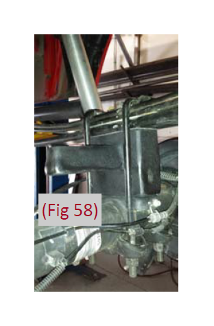
91. Raise the axle and block up to the spring while aligning the center pins. Fasten the spring and block assembly with the provided u‐bolts, high nuts and washers. Snug the u‐bolts firmly, they will be torqued with the weight of the vehicle on the springs. (Fig 58)
92. Repeat installation procedure on the driver’s side of the vehicle.
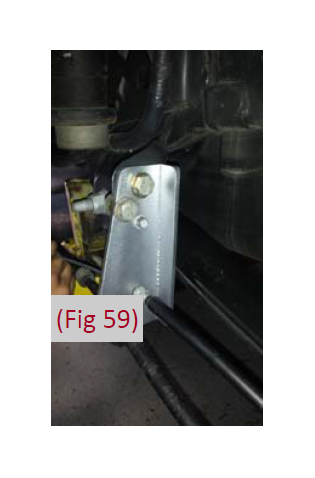
93. Install the provided parking brake relocation bracket (#48‐ 2620) to the driver’s side front spring hanger using provided 1/2” bolts, washers, and nuts. Late 2012 models and newer will require the retaining wire to be bolted to the bracket with 1/4” hardware. (Fig 59)
94. Reconnect the parking brake cable at the junction. When reconnected, remove the clamp to allow the cable to return to its normal tension. Attach the parking brake cable through the relocation bracket through the slot in the bottom.
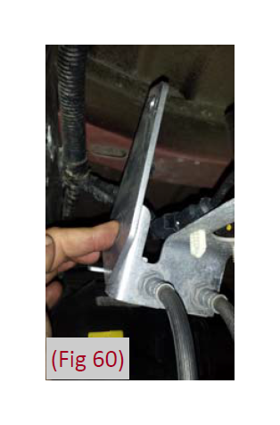
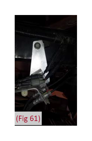
95. Install the provided brake line relocation bracket (#48‐2610) to the driver’s side frame rail with the OE brake line bracket bolt. (Fig 60, 61) Torque to 15 ft‐lbs.
96. Attach the brake line to the relocation bracket with the supplied 5/16” bolt, nut, and washers. It may be necessary to rotate the OE brake line clip bracket to have the lines face ‘down’ for adequate slack. Torque to 15 ft‐lbs.
97. Install the extended length shock absorbers with the OE hardware. Torque to 60 ft‐lbs.
98. Check all brake lines, hoses, and wires for proper slack and clearance while suspension is at full droop.
99. If the vehicle is equipped with EPAS, reconnect the power steering control module connector.
100. If the vehicle is equipped with hydraulic rack and pinion steering, top off and bleed the hydraulic fluid at this time.
101. Install the rear wheels and tires and lower the vehicle to the ground.
102. Jounce the Front & Rear of the vehicle to settle the suspension.
103. Torque the u‐bolts to 100‐120 ft‐lbs.
Some Final Checks
104. Check all hardware for proper torque specifications.
105. Torque lug nuts to wheel manufacturer specifications.
106. Check tire air pressure to manufacturer specifications.
107. A complete four wheel vehicle alignment is necessary.
108. Re‐adjust headlights to compensate for increased ride height.
109. Cycle Steering from lock to lock and check for any interference of wheels, tires, brake lines, hoses, wires, etc. and ensure adequate clearance throughout the suspension cycle.
110. Install all warning tags and decals as directed: Rear view mirror hanging warning card – Hang from rear view mirror to warn new driver of vehicle modification. Lifted Truck Warning Decal – Apply decal to upper left hand corner of the inside of the windshield facing the driver.
111. Give all installation instructions, warranty information, and all remaining literature to the end user and keep with vehicle records.
112. ***Re‐Check all hardware for proper torque value after 500 miles, and then periodically at each service interval thereafter.***
Final Checks & Adjustments
Post Installation Warnings: Once the vehicle is lowered to the ground, check all parts which have rubber or urethane components to insure proper torque. Torque wheels to factory specs. Move vehicle backwards and forwards a short distance to allow suspension components to adjust. Turn the front wheels completely left then right and verify adequate tire, wheel, brake line, and ABS wire clearance. Test and inspect steering, brake and suspension components for tightness and proper operation. Inspect brakes hoses and ABS lines for adequate slack at full extension. Failure to perform the post inspection checks may result in vehicle component damage and/or personal injury or death to driver and/ or passengers. Test drive vehicle and re-check the torque of all fasteners and re-torque wheels on vehicle. Re-adjust headlamps.
Vehicle Handling Warning: Vehicles with larger tires and wheels will handle differently than stock vehicles. Take time to familiarize yourself with the handling of your vehicle.
Wheel Alignment/Headlamp Adjustment: It is necessary to have a proper and professional wheel alignment performed by a certified alignment technician. Align the vehicle to factory specifications. It is recommended that your vehicle alignment be checked after any off-road driving. In addition to your vehicle alignment, for your safety and others, it is necessary to check and adjust your vehicle headlamps for proper aim and alignment
Vehicle Re-Torque and Safety Inspection: Upon completion of all services and adjustments performed on your vehicle, and within 50 miles of driving, check to ensure all fasteners and hardware are properly torqued to specification as noted in the vehicles factory service manual or the torque chart included.
